Fixing structure of secondary hanger for plating PCB (Printed Circuit Board)

A printed circuit board and fixed structure technology, applied in electrolysis process, electrolysis components, etc., can solve problems such as uneven plating, detachment, copper slag, etc., achieve the effect of improving copper slag problem, improving product quality, and ensuring uniformity

Inactive Publication Date: 2011-10-19
竞陆电子(昆山)有限公司
View PDF6 Cites 2 Cited by
  • Summary
  • Abstract
  • Description
  • Claims
  • Application Information

AI Technical Summary

Problems solved by technology

When the board is not fully hung with the hanger, the board is generally fixed on the secondary hanger located in the middle of the hanger, and the board is not fixed on the secondary hanger at both ends of the hanger. During electroplating, the secondary hanger and the board are immersed in the Electroplating in the electroplating solution, the secondary hanger without boards at both ends will also be plated with copper; and when the copper on the secondary hanger at both ends reaches a certain thickness, it will be in the form of copper particles from the secondary hanger The surface is detached, so that there is copper slag in the electroplating solution, which affects the quality of electroplating; and when the copper on the secondary racks at both ends is deposited to a certain thickness, the copper ions near the secondary racks at both ends will move to the middle. Cause uneven plating, so that the thickness of the coating on the boards near both ends is greater than the thickness of the coating on the middle board, thus affecting product quality

Method used


Image

  • Fixing structure of secondary hanger for plating PCB (Printed Circuit Board)
  • Fixing structure of secondary hanger for plating PCB (Printed Circuit Board)
  • Fixing structure of secondary hanger for plating PCB (Printed Circuit Board)

Examples


Embodiment

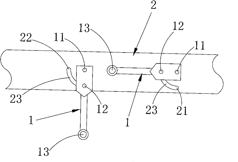
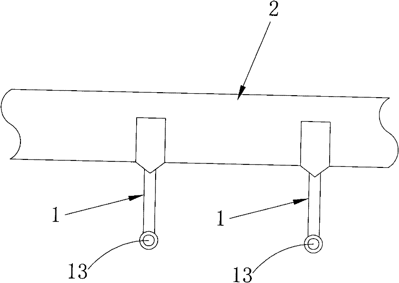
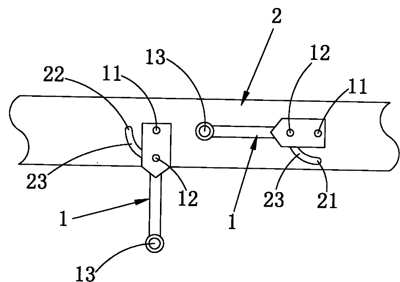
[0013] Embodiment: a fixing structure of a secondary hanger for printed circuit board electroplating, several secondary hangers 1 are fixed on the copper plate 2 at intervals, and one end of the secondary hanger has a fixed point that is fixedly connected with the copper plate. The other end of the secondary hanger has a locking point 13 for fixing the board. One end of the secondary hanger 1 has two fixed points, which are the first and second fixed points 11 and 12. The second hanger is fixed at the first Point 11 is rotatably connected to the bronze medal 2, and the secondary hanger can rotate around the first fixed point. The position on the bronze medal vertically below the first fixed point 11 has a first positioning point 21. The bronze medal The position located in the horizontal direction of the first fixed point and having a horizontal distance from the first fixed point has a second positioning point 22, and the first fixed point 11 is far from the second fixed point...


PUM


Abstract

The invention discloses a fixing structure of a secondary hanger for plating a PCB (Printed Circuit Board). The secondary hanger is capable of rotating around a first fixed point by setting two fixed points on the secondary hanger and setting two locating points on a copper medal; when the secondary hanger is rotated to the second fixed point and is overlapped with the first locating point on the copper medal, the secondary hanger is firmly connected with the copper medal; at the moment, the secondary hanger is vertically downwards for normal electroplating; when the secondary hanger is not fixed with a board, the secondary hanger is rotated to the second fixed point and is overlapped with the second locating point on the copper medal, and then the secondary hanger is firmly connected with the copper medal; at the moment, the secondary hanger is fixed horizontally; when in electroplating, the secondary hanger which is not fixed with the board is fixed horizontally, and the secondary hanger is prevented from soaking in electroplating liquid and participating the electroplating; therefore, the secondary hanger which is not fixed with the board is prevented from plating copper, the problem of copper slag can be effectively improved, the copper resource is saved, the uniformity of plating can be further guaranteed, and the product quality is improved.

Description

technical field [0001] The invention relates to a structural improvement of a hanger used for electroplating printed circuit boards, in particular to an improvement in the fixing structure of a secondary hanger on the hanger for electroplating. Background technique [0002] Electroplating is to immerse the plated part in the plating solution of metal salt as the cathode, and the conductor or semiconductor as the anode. After the power is turned on, the desired coating is deposited on the surface of the plated part. [0003] Electroplating is an essential part of the printed circuit board (PCB) production process. At present, in the electroplating production process of printed circuit boards, the hanger is an indispensable tool. Its main function is to fix the board to be electroplated and connect the electrode (cathode) so that the current is evenly transmitted to the board. The chemical principles plate the copper onto the surface of the board. Reasonable selection of han...

Claims


Application Information

Patent Timeline
Patent Type & Authority Applications(China)
IPC IPC(8): C25D17/08
Inventor 李泽清
Owner 竞陆电子(昆山)有限公司
Why Eureka
Try Eureka