
An airtight control device and method applied to electroplating grinding wheel

A control device and airtight technology, applied in the direction of electrolytic coating, coating, etc., can solve problems such as electroplating failure and inability to ensure airtight sealing

Active Publication Date: 2021-09-14
苏州浩耐特磨具有限公司
View PDF20 Cites 0 Cited by
  • Summary
  • Abstract
  • Description
  • Claims
  • Application Information

AI Technical Summary

Problems solved by technology

[0006] One of the objectives of the present invention is to solve the problem that the protection fixture structure in the prior art cannot ensure that the sealing protection pad seals the non-electroplating surfaces on both sides of the electroplating grinding wheel, and there is a possibility of electroplating failure

Method used


Image

  • An airtight control device and method applied to electroplating grinding wheel
  • An airtight control device and method applied to electroplating grinding wheel
  • An airtight control device and method applied to electroplating grinding wheel

Examples


Embodiment 1

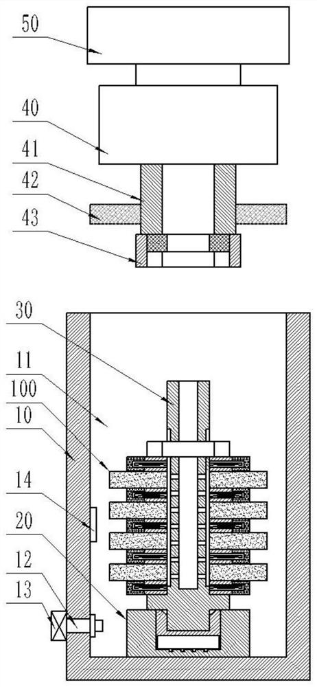
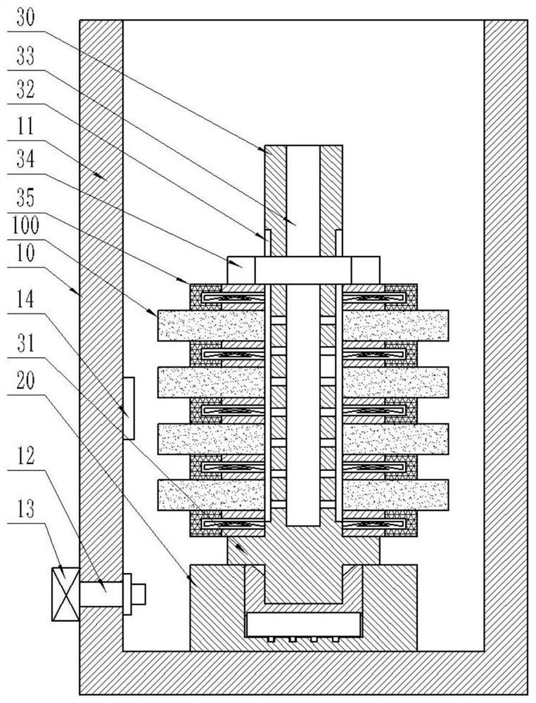
[0072] An airtight control device applied to electroplated grinding wheels, wherein, such as Figure 1-5 As shown, it includes: an airtight control cylinder 10 , an engaging seat 20 , a mandrel mechanism 30 , a telescopic docking mechanism 40 , and a driving motor 50 .

[0073] The airtight control cylinder 10 has: an airtight cavity 11 , a booster port 12 , a booster pump 13 , and an air pressure sensor 14 .

[0074] The booster port 12 communicates with the airtight chamber 11 , the booster pump 13 communicates with the booster port 12 , and the air pressure sensor 14 is installed on the side wall of the airtight chamber 11 .

[0075] The joint seat 20 is installed at the inner bottom of the airtight cavity 11 . The joint seat 20 is coaxial with the airtight control cylinder 10 .

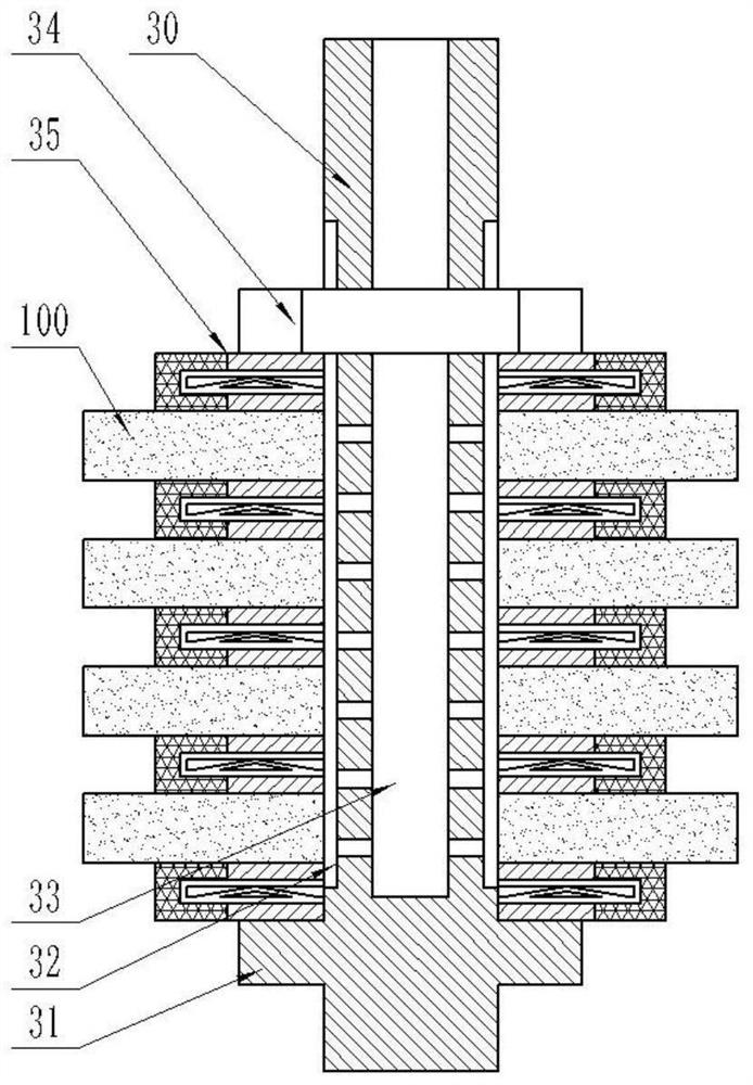
[0076] The mandrel mechanism 30 has: a mandrel, a fixed block 31 , a sealing protection pad 35 , and a locking nut 34 .

[0077] The mandrel is snapped into the joint seat 20, and the outer sur...

Embodiment 2

[0093] An airtight control device applied to an electroplated grinding wheel, wherein it has the same characteristic structure as that of Embodiment 1, such as Figure 7-9 As shown, the joint base 20 is composed of a docking base 21 and a protection base 22 , and the protection base 22 is movably installed in the docking base 21 .

[0094] The bottom of the docking base 21 has an annular groove 211 and a vertical groove 212 communicating with the annular groove 211 . A coil spring 23 is provided under the protection seat 22 , and a sliding block 231 slidingly connected with the vertical slot 212 is provided under the coil spring 23 .

[0095] When the lock nut 34 exerts pressure on the sealing protection pad 35, the mandrel is subjected to rotational stress, and the mandrel transmits the stress to the protection seat 22, and the protection seat 22 transmits the force to the coil spring 23, and the sliding block at the bottom of the coil spring 23 231 is blocked by the vertica...

Embodiment 3

[0097] An airtight control method applied to an electroplated grinding wheel, comprising the following steps:

[0098] Loading, set the electroplated grinding wheel 100 and the sealing protection pad 35 on the mandrel, so that the sealing protection pad 35 is arranged between two adjacent electroplating grinding wheels 100 and axially outside the outermost electroplating grinding wheel 100;

[0099] Clamping, insert the bottom end of the mandrel into the joint seat 20 at the bottom of the airtight chamber 11 in the airtight control cylinder 10, and rely on the locking nut 34 corresponding to the axial upper end of the mandrel to seal and protect each electroplated grinding wheel 100 The pad 35 is axially clamped, wherein the fixed block 31 at the axial lower end of the mandrel restricts the sealing protection pad 35 on it;

[0100] Docking, start the telescopic docking mechanism 40 above the airtight control cylinder 10 to drive the telescopic shaft 41, the sealing piston 42 a...


PUM


Abstract

The invention discloses an airtight control device applied to electroplating grinding wheels, relates to the technical field of electroplating grinding wheel processing equipment, and comprises: an airtight control cylinder, a mandrel mechanism, a telescopic butt joint mechanism, and a drive motor. By implementing pressurized gas in the airtight airtight chamber, the air pressure sensor can measure whether the gas pressure in the airtight chamber after pressurization changes, and after the gas pressure in the airtight chamber changes, the sealing effect of the sealing protection pad will be confirmed. Bad, the gas measuring groove is set on the mandrel to guide the leaked gas to discharge, and at the same time, the tightening cap under the telescopic docking mechanism can drive the lock nut to press the sealing protection pad to seal the non-electroplating of the electroplating grinding wheel until the gas pressure in the airtight cavity No change. The sealing condition of the sealing protection pad to the electroplated grinding wheel is measured through the pressure test, and after the poor sealing is detected, the lock nut can be further controlled to exert pressure on the sealing protection pad to ensure the sealing effect and avoid the electroplating grinding wheel during electroplating. The non-plated side is plated.

Description

technical field [0001] The invention relates to the technical field of electroplating grinding wheel processing equipment, in particular to an airtight control device applied to electroplating grinding wheels. Background technique [0002] The electroplated grinding wheel is a processing tool suitable for high-speed and ultra-high-speed grinding. It includes a substrate and a coating formed by co-depositing metal nickel ions, diamond or cubic boron nitride and other abrasives on the plated surface of the substrate through the electroplating process. The coating is located at the edge of the substrate. Therefore, in the process of manufacturing the electroplated grinding wheel, it is necessary to cover the non-electroplated surfaces on both axial sides of the substrate that do not require electroplating for protection. [0003] In the prior art, the covering of the non-electroplated surface generally adopts the method of pasting self-adhesive PVC paper, or adopts the method o...

Claims


Application Information

Patent Timeline
Patent Type & Authority Patents(China)
IPC IPC(8): C25D5/02C25D7/00C25D15/00
CPCC25D5/022C25D7/00C25D15/00
Inventor 谭志平
Owner 苏州浩耐特磨具有限公司
Learn More