
Dehumidifying and cooling system of offshore wind generating set

A technology for wind turbines and cooling systems, applied to wind turbine components, wind engines, wind power generation, etc., which can solve problems such as damage, air insecurity, and limited cooling effects, and achieve reliability and long-term service life. Working environment, the effect of avoiding salt spray corrosion

Active Publication Date: 2011-10-19
GUANGZHOU INST OF ENERGY CONVERSION - CHINESE ACAD OF SCI
View PDF5 Cites 7 Cited by
  • Summary
  • Abstract
  • Description
  • Claims
  • Application Information

AI Technical Summary

Problems solved by technology

[0007] This cooling method uses air as the final cooling source. Due to the small mass flow rate of the air, the cooling effect is limited. When the capacity of the unit increases and the heat generation is greater, it is difficult to meet the cooling requirements.
[0008] At the same time, if this cooling system is used in offshore wind turbines, it will cause more serious problems
Because the air on the sea surface is humid and contains salt, it is easy to cause corrosion and damage to the air-cooled heat exchanger, and the service life is greatly shortened
[0009] Due to maintenance and other reasons, the air inside the unit cannot be completely isolated from the outside air, and there are hidden dangers and dangers of humid air corroding equipment.

Method used


Image

  • Dehumidifying and cooling system of offshore wind generating set
  • Dehumidifying and cooling system of offshore wind generating set

Examples


Embodiment

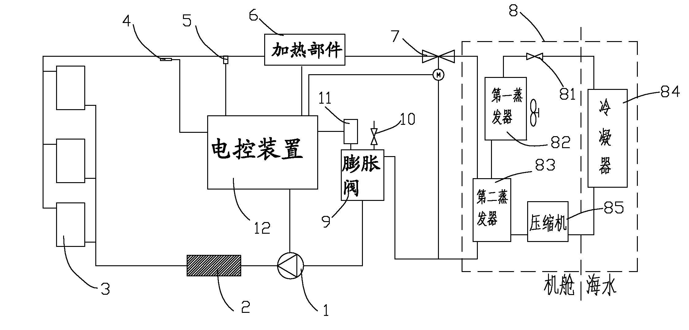
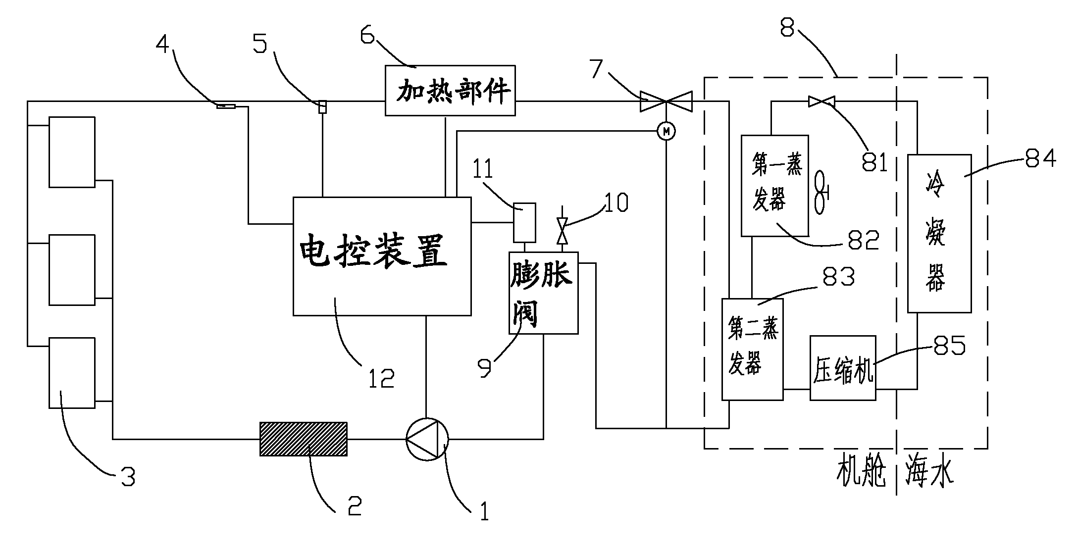
[0040] see figure 1 As shown, the cooling system of the offshore wind power generating set includes a circulation pump 1, a filter device 2, a radiator 3, a heating component 6, a three-way solenoid valve 7, and an expansion tank 9 arranged in the nacelle and connected end to end in order to form a circuit. ; The pipeline connected between the radiator 3 and the heating component 6 is provided with a temperature detection device 4 and a pressure detection device 5 in sequence; it also includes a vapor compression refrigeration unit 8, which includes a throttling element 81 located in the engine room, The first evaporator 82, the second evaporator 83, the compressor 85, and the condenser 84 arranged in the seawater, the throttling element 81, the first evaporator 82, the second evaporator 83, the compressor 85, the condenser 84 They are connected in sequence to form a circuit; both ends of the second evaporator 83 are also connected to the three-way solenoid valve 7 and the exp...


PUM


Abstract

The invention discloses a dehumidifying and cooling system of an offshore wind generating set, comprising a circulating pump, a filtering device, a radiating device, a heating part, a tee-joint magnetic valve and a expanding tank, which are arranged in an engine cabin, connected in sequence end to end and form a loop; a temperature detecting device and a pressure detecting device are sequentially arranged on a pipeline connected between the radiating device and the heating part; the system also comprises a steam compressing refrigerating unit which comprises a throttling element, a first evaporator, a second evaporator and a compressor which are arranged in the engine cabin, as well as a condenser arranged in sea water; the throttling element, the first evaporator, the second evaporator, the compressor and the condenser are connected in sequence to form a loop; and two ends of the second evaporator are further connected with the tee-joint magnetic valve and the expanding tank respectively. As the refrigerating output of the refrigerating unit is large, the heating capacity of a wind generating unit can be radiated rapidly, so that the cooling requirement of an MW-stage wind generating unit with larger heating capacity is ensured, and the system is applicable to the development and the application of a wind power generation unit with larger capacity.

Description

technical field [0001] The invention relates to the field of wind power generation, in particular to a dehumidification and cooling system for offshore wind power generators. Background technique [0002] Wind energy is a clean and renewable energy source. Since 1996, the global installed capacity of wind power has grown at an average annual rate of 30%, exceeding 158 million kW by the end of 2009. my country's wind energy installed capacity is 25 million kW, ranking second in the world. [0003] When the wind turbine is running, a large amount of heat will be generated on the three major components of the gearbox, generator and inverter controller. If the heat is not discharged in time, the efficiency of the wind turbine will be greatly reduced, and eventually it will be paralyzed. Therefore, it is an indispensable and important measure to ensure the long-term and normal operation of wind turbines to be equipped with a cooling system with excellent performance and rapid c...

Claims


Application Information

Patent Timeline
IPC IPC(8): F03D11/00B01D53/26B01D5/00F03D80/00F03D80/60
CPCY02E10/72Y02P70/10
Inventor 冯自平高日新黄冲何世辉林用满韩颖
Owner GUANGZHOU INST OF ENERGY CONVERSION - CHINESE ACAD OF SCI
Learn More