
Illumination structure

A lighting structure and technology of light-emitting diodes, applied in lighting devices, lighting and heating equipment, lighting device components, etc., can solve problems such as high cost, light decay, and cost can not be effectively controlled, so as to save costs and reduce damage Effect

Inactive Publication Date: 2011-10-19
王湘云
View PDF0 Cites 4 Cited by
  • Summary
  • Abstract
  • Description
  • Claims
  • Application Information

AI Technical Summary

Problems solved by technology

[0004] Because high-power LEDs (for example: LEDs for lighting) emit extremely high heat, the heat emitted by the chip will be directly conducted to the fluorescent mixed glue, making the basic colloid (usually silica gel), phosphor, and activated The phosphor is baked under high heat for a long time, which makes the phosphor easy to deteriorate and deteriorate due to the high temperature generated by the LED, and at the same time produces the phenomenon of light decay, while the fluorescent mixed glue is prone to brittle cracking for a long time, which is the most common problem in existing LEDs. shortcoming
[0005] Secondly, in order to slow down the impact of the above-mentioned high-power LED's high heat on the fluorescent mixture and phosphor, it is necessary to develop and use high-temperature-resistant phosphors and colloids, which keeps the cost of LEDs high, which is another existing disadvantage.
[0006] After the LED is installed on the chip, it is coated and sealed on the chip with a mixed colloid containing fluorescent powder and combined as a whole. Therefore, after the LED is coated with phosphor, optical testing needs to be carried out again. Once the light saturation is deviated or the color is distorted, it will be discarded together with the excellent outer seal and the chip, so that the pass rate cannot be improved and the cost cannot be reduced. Effective control is another existing shortcoming

Method used


Image

  • Illumination structure
  • Illumination structure
  • Illumination structure

Examples


Embodiment Construction

[0024] In order to enable your review committee members to clearly understand the content of the present invention, only the following descriptions are used together with the drawings, as follows:

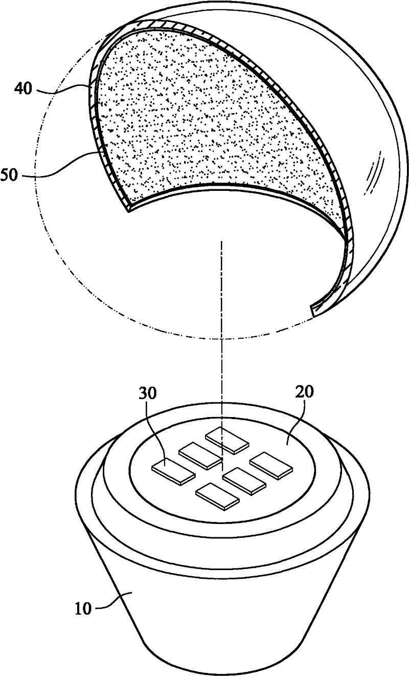
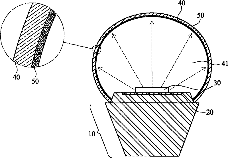
[0025] Please see figure 1 , figure 2 As shown, the present invention at least includes:

[0026] A lamp holder heat dissipation module 10 is provided with a circuit board 20 at one end, and at least one high-power light-emitting diode chip 30 is provided on the circuit board 20, and the light-emitting diode chip 30 has two implementation modes, the first One is a light-emitting diode (LED) bare chip that simply emits colored light, that is, a bare chip that does not have phosphor powder or protective sealant (Lens), so it can be one of blue light, red light, and green light; A second embodiment of diode die 30 is a bare die capable of emitting high power ultraviolet (UV) light.

[0027] The above-mentioned heat dissipation module 10 of the lamp holder can be integrally formed...


PUM


Abstract

The invention relates to an illumination structure. A light-emitting diode (LED) chip is arranged in a lamp holder radiating module and is an LED bare chip without fluorescent powder or sealant; a lamp shade covers the upper side of the LED chip of the lamp holder radiating module; the inner wall of the lamp shade is uniformly coated with a fluorescent coating; a space is reserved between the LED chip and the fluorescent coating; and the fluorescent coating absorbs light rays emitted by the LED chip to emit illumination white light. Therefore, the problem that the lighting effect of the fluorescent powder on the conventional LED chip is attenuated is solved, and yield and economic benefits can be improved.

Description

technical field [0001] The invention relates to an illumination structure, which refers to a design of making an illumination structure body in a non-contact manner between a bare chip of a light-emitting diode and phosphor powder. Background technique [0002] The application of light-emitting diodes (LEDs) has been very extensive and has gradually become more diversified. The basic structure of LEDs currently used in lighting, such as image 3 As shown, it is the first kind of existing structure, mainly a chip is arranged in an enclosed outer package (outer package), and a fluorescent compound glue is sealed on the surface of the chip, and the inside of the fluorescent compound glue is Contains: basic colloid (generally silica gel), fluorescent powder, activator, etc. The fluorescent mixed glue is sealed above the outer seal and is in direct or indirect contact with the chip, so when the chip emits light, The light passes through the protective lens and reacts with the flu...

Claims


Application Information

Patent Timeline
IPC IPC(8): F21S2/00F21V19/00F21V17/00F21V3/04F21V9/10F21V3/02F21Y101/02F21K9/232F21V9/40F21Y115/10
Inventor 王湘华
Owner 王湘云
Learn More