Vertical convector radiator and vertical convector radiating down lamp

A technology of vertical convection and heat sink, which is applied in the direction of lighting and heating equipment, semiconductor devices of light-emitting elements, cooling/heating devices of lighting devices, etc., and can solve problems such as poor heat dissipation effect and heat island effect of passive radiators, and achieve Save interior decoration costs, avoid the heat island effect, and improve the effect of heat dissipation

Active Publication Date: 2011-10-19
KINGSUN OPTOELECTRONIC CO LTD
View PDF8 Cites 14 Cited by
  • Summary
  • Abstract
  • Description
  • Claims
  • Application Information

AI Technical Summary

Problems solved by technology

[0007] One of the technical problems to be solved by the present invention is to provide a vertical convection radiator, which so

Method used


Image

  • Vertical convector radiator and vertical convector radiating down lamp
  • Vertical convector radiator and vertical convector radiating down lamp
  • Vertical convector radiator and vertical convector radiating down lamp

Examples


Embodiment 1

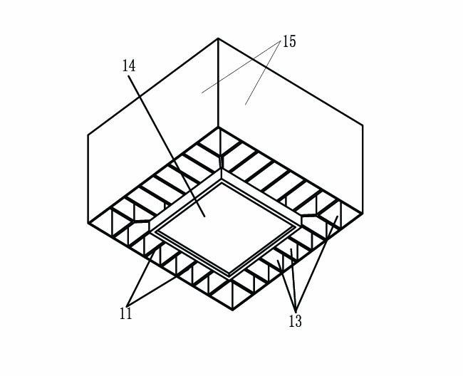
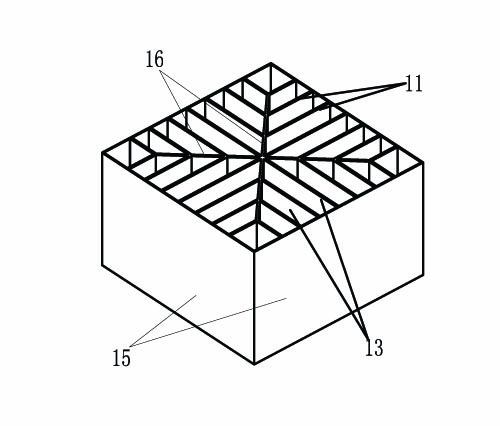
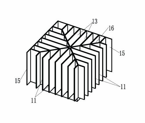
[0035] The vertical convection radiator of this embodiment improves the structure of the existing aluminum extruded radiator based on the "chimney effect". The structure of the improved vertical convection radiator is as follows figure 1 with figure 2 As shown, a plurality of heat dissipation fins 11 are included, a frame 15 and a connecting rib 16 are also included, and a light source mounting part is provided with a mounting position 14 on the light source mounting part. Such as image 3 As shown, the obvious difference between the vertical convection heat sink of this embodiment and the existing aluminum extruded heat sink is that most of the gaps formed between the heat dissipation fins 11 and the frame 15 and the connecting ribs 16 run through the entire Radiator, thereby forming a number of convection channels 13. When the vertical convection radiator is working, the cold air at the bottom of the vertical convection radiator (near the heat source) is continuously heated a...

Embodiment 2

[0044] The vertical convection radiator of the present invention can have several deformations in specific shapes, such as Image 6 with Figure 7 What is shown is another vertical convection heat sink provided by this embodiment.

[0045] The biggest difference between the vertical convection radiator in this embodiment and the first embodiment is that the overall shape is cylindrical. The heat dissipation fins radiate uniformly from the center to the outside. The outermost is a cylindrical frame 15 with two cylindrical connecting ribs 16 in the middle, and the connecting ribs 16 and the frame 15 are arranged concentrically. Of course, the core essence is that the gaps between the radiating fins and the frame 15 and the connecting ribs 16 form a convection channel 13 passing through the upper and lower sides of the radiator, which can also form a "chimney effect", thereby improving the heat dissipation effect. Correspondingly, the light source mounting component and the mounting...

Embodiment 3

[0047] This embodiment provides a vertical convection radiator such as Figure 8 As shown, the difference from the second embodiment is that the aluminum substrate (not shown in the figure) on which the LED is mounted is not sleeved on the periphery of the frame 15 but is arranged inside the frame 15. Moreover, the cylindrical connecting rib 16 as in the second embodiment is not provided.


PUM


Abstract

The invention discloses a vertical convector radiator and comprises a vertical convector radiating down lamp of the vertical convector radiator. The vertical convector radiator comprises light source installation parts and a plurality of heat radiating fins of which the lower ends are connected with the light source installation parts in a heat conducting mode, wherein the vertical convector radiator comprises a plurality of convection passageways which penetrates through and is vertical to the upper surface and the lower surface of the convector radiator. When the vertical convector radiator in the technical scheme adopted operates, the lower end of the heat dissipation rectangular fin continuously heats the neighbouring air and the air rises, simultaneously, the neighbouring cold air can continuously complement to generate convection, thus the vertical convector radiator of the specific implement method can form a higher air velocity field even under the passive voice radiating condition, full heat exchange is generated between the cold air and the heat dissipation rectangular fin surface of the vertical convector radiator, the heat is rapidly take away, thereby avoiding the generation of the heat island effect in the bottom of the radiator, and the heat dissipation capacity is greatly improved.

Description

Technical field [0001] The invention relates to the technical field of lighting and heat dissipation, in particular to a vertical convection radiator and a vertical convection radiating downlight with the radiator. Background technique [0002] In recent years, the technology of LED lighting has developed rapidly, and high-power LED lighting has entered the application stage, but the heat dissipation problem has always been one of the core problems of high-power LED lighting to be resolved. [0003] As far as the light efficiency level of existing LEDs is concerned, 70% to 80% of the input electric energy will be converted into heat. Moreover, due to the small size of the LED chip, poor heat dissipation will cause the temperature of the LED chip to rise sharply, causing problems such as uneven thermal stress distribution, reduced chip luminous efficiency, and reduced phosphor lasing efficiency. In addition, poor heat dissipation will result in a higher temperature rise of the chip...

Claims


Application Information

Patent Timeline
IPC IPC(8): F21V29/00F21S2/00
CPCF21V29/74F21V29/83F21Y2115/10
Inventor 唐林涛
Owner KINGSUN OPTOELECTRONIC CO LTD
Why Eureka
Try Eureka