
Dragging motor coupling cooling system and method

A technology for driving motors and cooling systems, applied in cooling/ventilation devices, electrical components, electromechanical devices, etc., can solve the problems of easy formation of heat island effect, reduction of cooling system efficiency, poor energy saving effect, etc.

Active Publication Date: 2021-07-30
HUANENG CLEAN ENERGY RES INST
View PDF13 Cites 0 Cited by
  • Summary
  • Abstract
  • Description
  • Claims
  • Application Information

AI Technical Summary

Problems solved by technology

For the drag motor, on the one hand, its large loss must be considered, and on the other hand, the environmental conditions of the drag motor must be considered. However, for the existing wind turbine cooling technology, it does not mention that the drag motor is suitable At the same time, for excessive loss, when providing cooling load for heat dissipation, the energy consumption of the cooling system should be taken into account
[0006] To sum up, the cooling system of the drag motor in the prior art cannot meet the cooling requirements of large wind turbines, and has the problems of taking up a large space, easily forming a heat island effect, reducing the efficiency of the cooling system, and poor energy saving effect

Method used


Image

  • Dragging motor coupling cooling system and method
  • Dragging motor coupling cooling system and method
  • Dragging motor coupling cooling system and method

Examples


Embodiment Construction

[0044] The present invention will be further described in detail below in conjunction with specific embodiments, which are explanations of the present invention rather than limitations.

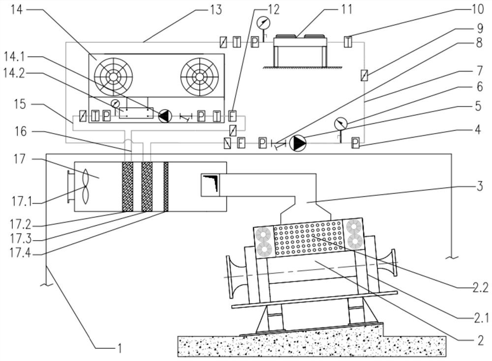
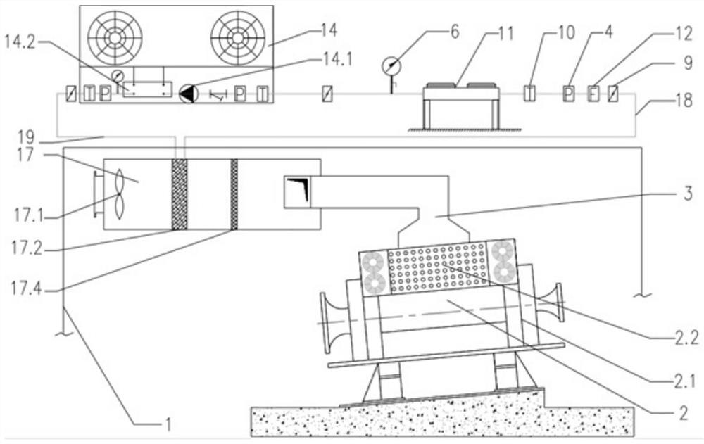
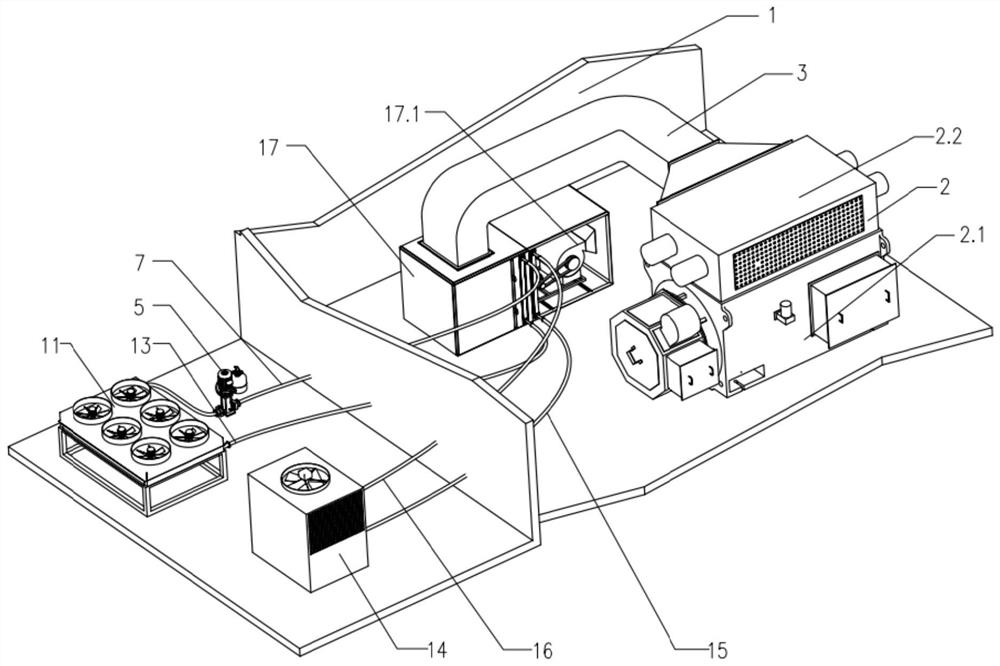
[0045] A driving motor coupling cooling system of the present invention includes a test bench building 1, a driving motor 2, a return air duct 3, a pressure transmitter 4, a dry cooler pump station 5, a pressure gauge 6, a first cooling return pipe 7, Filter 8, valve 9, temperature sensor 10, dry cooler 11, flow sensor 12, first cooling water supply pipe 13, air-cooled chiller 14, second cooling water supply pipe 15, second cooling return water pipe 16, air conditioning wind Chamber 17, return water pipeline 18, water supply pipeline 19.

[0046] The driving motor 2 includes a motor 2.1 and an air-to-air cooler 2.2. The air-cooled chiller 14 includes a water chiller water pump 14.1 and a heat exchanger 14.2 in the chiller. The dragging motor 2 is inclined relative to the bottom surface.

[0...


PUM


Abstract

The invention discloses a dragging motor coupling cooling system and method. The system comprises a dragging motor, an air return pipe, a dry cooler pump station, a first cooling water return pipe, a dry cooler, a first cooling water supply pipe, an air-cooled water chiller, a second cooling water supply pipe, a second cooling water return pipe, an air conditioning air chamber, a water return pipeline and a water supply pipeline. The air-cooled water chiller comprises a water chiller water pump, a water chiller internal heat exchanger and a refrigerating system; the dragging motor comprises a motor and an air-air cooler, the motor is fixed on the ground, the air-air cooler is arranged on the motor, and the air return air pipe is connected with the air-air cooler and the air conditioning air chamber. When the dry cooler is connected with the air-cooled water chiller in series, an air chamber circulating fan and a second air-water heat exchanger are arranged in the air conditioning air chamber; when the dry cooler is connected with the air-cooled water chiller in parallel, an air chamber circulating fan, a second air-water heat exchanger and a first air-water heat exchanger are arranged in the air conditioning air chamber. The wind driven generator dragging motor can be effectively cooled.

Description

technical field [0001] The invention belongs to the technical field of wind power generating set cooling, in particular to a driving motor coupled cooling system and method. Background technique [0002] With the emergence of fossil energy crisis and environmental problems, the development and utilization of renewable energy has attracted more and more attention from all over the world, especially wind energy, as a clean and safe green energy, is of great significance to the sustainable development of human society. With the continuous increase of wind energy development and the rapid development of offshore wind power, the continuous increase of stand-alone capacity has become the development trend of international wind power generation. However, wind turbines are often located in remote and unattended areas, so higher requirements are placed on the stability, reliability and maintenance-free of the generator set. In view of the series of advantages of the permanent magnet ...

Claims


Application Information

Patent Timeline
IPC IPC(8): H02K9/10
CPCH02K9/10Y02E10/72
Inventor 蔡安民焦冲杨博宇李媛张林伟许扬郑磊
Owner HUANENG CLEAN ENERGY RES INST
Learn More