A multi-purpose pump system

A pump system and multi-purpose technology, applied in heat pumps, refrigeration components, refrigerators, etc., can solve problems such as pollution, leakage of organic working fluid, and lack of absorption heat energy for utilization

Active Publication Date: 2018-07-27
屹立顺通(山东)节能环保科技有限公司
View PDF10 Cites 0 Cited by
  • Summary
  • Abstract
  • Description
  • Claims
  • Application Information

AI Technical Summary

Problems solved by technology

[0005] The applicant's Chinese patent authorization announcement number is CN1036089C "pneumatic liquid pump" and the Chinese patent authorization announcement number is CN1069953C "pneumatic pump" two invention patents, which only use compressed air to lift and transport liquid, and do not have the ability to absorb the environment. The function of utilizing thermal energy
In addition, the applicant's Chinese patent authorization announcement number is CN102538296B "multipurpose thermal machinery" and Chinese patent authorization announcement number is CN103277937 "multipurpose heat pump" two invention patents, which have the ability to absorb heat in the environment for lifting and transporting Liquid, refrigeration, heating and other functions, but they are only based on organic working fluid and heat pump power cycle system using gas compressor, organic working fluid heat pump cycle still has the following disadvantages: (1) The cost of the compressor is relatively high, (2 ) There is a possibility of leakage of organic working fluid and contamination with the lifted fluid

Method used


Image

  • A multi-purpose pump system
  • A multi-purpose pump system
  • A multi-purpose pump system

Examples


Embodiment Construction

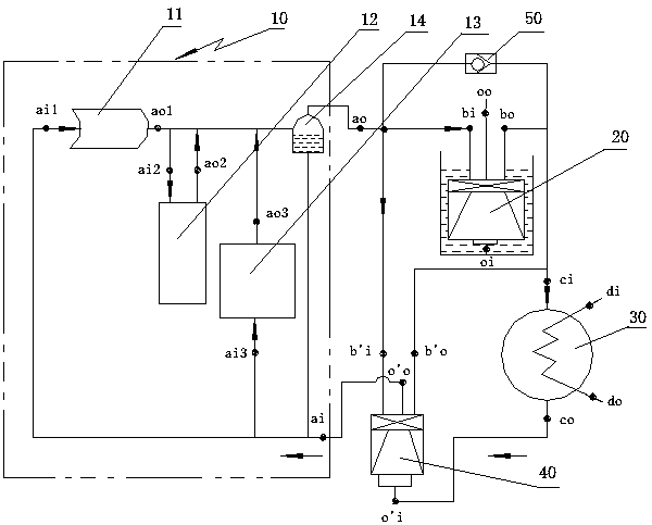
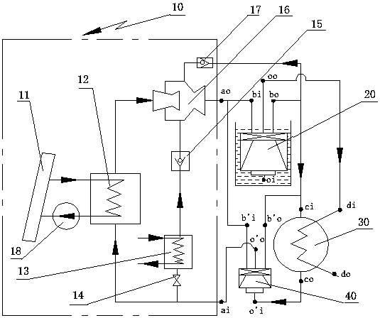
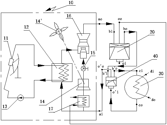
[0049] attached figure 1 The utility model is a multi-purpose pump system of the present invention that mainly absorbs and utilizes solar energy and is supplemented by other energy sources for transporting liquids and lowering the ambient temperature. The thermal power unit 10 is a thermal power generating subsystem that operates jointly with solar energy, auxiliary heat source, and heat storage. Groove 12, gas-liquid separator 14 etc. are formed, and solar heat collector 11 is connected in parallel with auxiliary energy steam generator 13, and heat storage tank 12 is connected on the air outlet pipeline of solar collector 11 and auxiliary energy steam generator 13, The inlet port of the gas-liquid separator 14 is connected in series with the common gas outlet port of the auxiliary energy steam generator 13 and the solar collector 11, and the gas outlet port of the gas-liquid separator 14 is used as the gaseous working medium gas outlet port ao of the thermal power unit 10 , ...


PUM


Abstract

A multi-purpose pump system, comprising a thermodynamic unit (10), a main pneumatic positive displacement pump (20), a condenser (30), a circulating pneumatic positive displacement pump (40), a pipeline and a working medium therein, wherein a fluid inlet of the thermodynamic unit (10) is connected to a fluid outlet of the circulating pneumatic positive displacement pump (40), an air outlet of the thermodynamic unit (10) is connected to an air inlet of the main pneumatic positive displacement pump (20), an air outlet of the main pneumatic positive displacement pump (20) is connected to an air inlet of the condenser (30), a fluid outlet of the condenser (30) is connected to a fluid inlet of the circulating pneumatic positive displacement pump (40), an air inlet and an air outlet of the circulating pneumatic positive displacement pump (40) are respectively connected in parallel to the air inlet and air outlet of the main pneumatic positive displacement pump (20), or are connected in series between the air outlet of the main pneumatic positive displacement pump (20) and the air inlet of the condenser (30). The multi-purpose pump system can be used not only to concentrate and absorb medium and low grade heat so as to lower the temperature of our planet, but also to elevatedly transport, heat and filter a fluid. The multi-purpose pump system may employ a steam working medium, or an organic working medium; it may absorb the heat from a single heat source, or from multiple heat sources synchronously. Moreover, the multi-purpose pump system takes fewer steps to convert energy and can be built at a low cost.

Description

technical field [0001] The invention belongs to the category of engineering thermodynamics and fluid machinery, and relates to heat energy conversion and utilization, in particular to a thermal power circulation pump system utilizing potential energy converted from medium and low-grade heat energy into liquid or gas. Background technique [0002] In the past, the number of people and animals on the earth was small, the living standard of human beings was low, farming was the mainstay, industry was underdeveloped, and energy consumption was low. The heat on the earth mainly came from solar radiation. During this period, the heat irradiated by the sun on the earth The heat absorbed, reflected and evaporated by the earth is in a stable natural dynamic equilibrium state. Nowadays (especially after the industrial revolution), the number of people and other animals (including artificial breeding) on ​​the earth has increased several times, and the energy and resources required for...

Claims


Application Information

Patent Timeline
Patent Type & Authority Patents(China)
IPC IPC(8): F25B30/02
CPCF25B30/06
Inventor 王超颖岑陈王政玉张玉芹
Owner 屹立顺通(山东)节能环保科技有限公司
Why Eureka
Try Eureka