
Heat collecting type combustor assembly with high efficiency and energy saving

A high-efficiency energy-saving, burner technology, applied in the direction of burner, gas fuel burner, combustion method, etc., can solve the problem that the waste heat of the burner assembly cannot be used, the ignition of the burner assembly is inconvenient, and the combustion of the burner assembly Insufficient problems, to achieve the effect of reducing heat loss, facilitating dispersion and preheating, and preventing heat loss

Inactive Publication Date: 2011-10-19
宫润涛
View PDF5 Cites 20 Cited by
  • Summary
  • Abstract
  • Description
  • Claims
  • Application Information

AI Technical Summary

Problems solved by technology

[0004] The purpose of the present invention is to provide a heat-collecting high-efficiency energy-saving burner assembly, to solve the problem that the waste heat of the traditional burner assembly cannot be utilized and the heat utilization rate is too low; and to solve the problem that the furnace in the traditional burner assembly is The problem of easy damage in high-temperature combustion; the technical problem of insufficient combustion and prone to gas blockage of the traditional burner assembly must be solved; the inconvenient ignition of the traditional burner assembly and the prone to air leakage and partial fire phenomenon must also be solved

Method used


Image

  • Heat collecting type combustor assembly with high efficiency and energy saving
  • Heat collecting type combustor assembly with high efficiency and energy saving
  • Heat collecting type combustor assembly with high efficiency and energy saving

Examples


Embodiment Construction

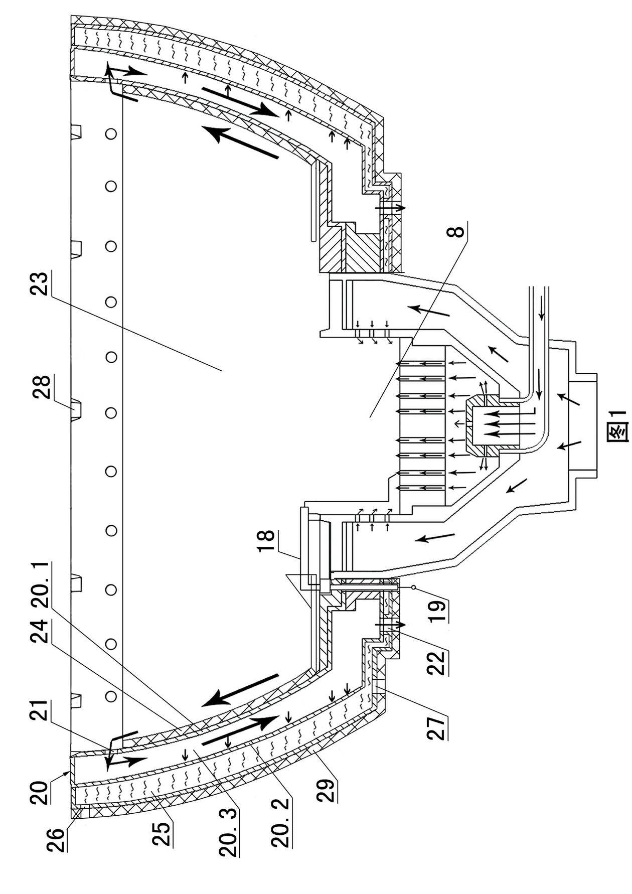
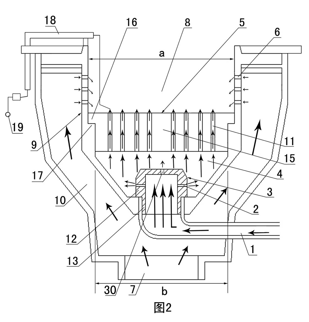
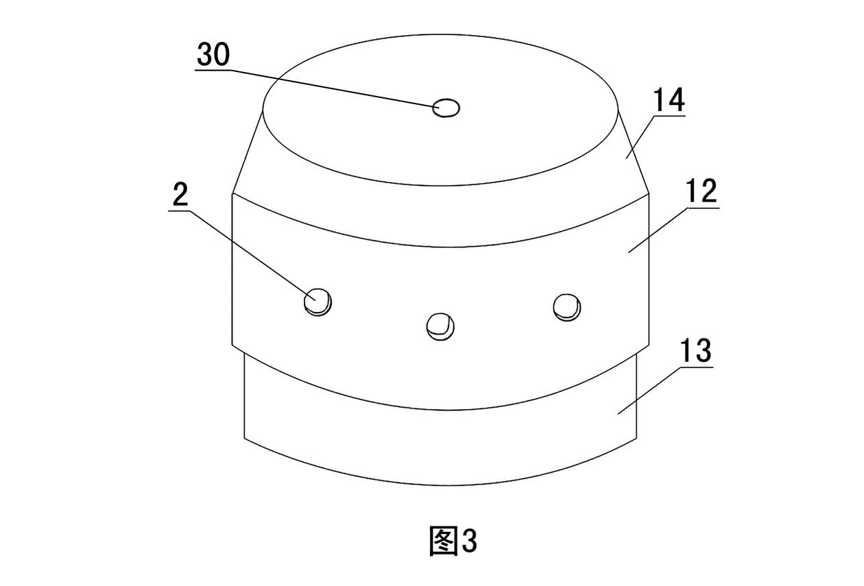
[0027] Examples see figure 1 , figure 2 As shown, this heat-collecting high-efficiency energy-saving burner assembly includes a burner and a furnace, wherein the burner includes a burner seat 9 and a gas preheating split combustion disc 5 placed on the burner seat 9. Below the gas preheating split combustion disc 5, the bottom of the burner seat 9 is provided with an air supply hole 1 communicated with the gas pipeline; The air outlet 6, the outer surface of the burner seat 9 is provided with an air supply channel 10, the lower part of the air supply channel 10 has an air inlet 7, and the upper part of the air supply channel 10 communicates with the air outlet 6, and the air outlet 6 can be arranged from top to bottom 2 to 4 rows, in this embodiment, 3 rows are provided.

[0028] see figure 1, the furnace includes a furnace side wall 20, the furnace side wall 20 is a hollow structure, including an inner side wall 20.1, an outer side wall 20.2 and an air cavity 20.3 sandwic...


PUM

PropertyMeasurementUnit
The inside diameter ofaaaaaaaaaa
Diameteraaaaaaaaaa

Abstract

The invention discloses a heat collecting type combustor assembly with high efficiency and energy saving, comprising a combustor and a hearth, wherein the hearth has a hearth side wall; the hearth side wall is of a hollow structure, including an inner side wall, an outer side wall and an air cavity clamped between the inner side wall and the outer side wall; the upper part of the inner side wall is equipped with a waste gas inlet hole communicated with the air cavity; the lower part of the outer side wall is provided with a waste gas outlet hole communicated with the air cavity; an afterheat collecting water jacket is tightly attached on the outer side surface of the outer side wall; the upper part of the afterheat collecting water jacket is equipped with a water inlet communicated with awater inlet pipe while the lower part thereof is provided with a water outlet communicated with a water outlet pipe; and an energy collecting anti-corrosion inner jacket is placed on the inner side of the hearth side wall, and is of a round sleeve shape with large top and small bottom. The combustor assembly in the invention has good energy saving effect and high economic benefit, and combustion effect better than that of the traditional combustor assembly, thus the consumption of the fuel can be reduced efficiently, and the hot water can be provided to the kitchen.

Description

technical field [0001] The invention relates to a commercial burner assembly, in particular to a commercial burner assembly used on a Chinese frying stove. Background technique [0002] The traditional burner assembly is divided into two categories, one is the household burner assembly, and the other is the commercial burner assembly. If the traditional commercial burner assembly is divided by combustion method, it is generally divided into direct mixing type and atmospheric mixing type. The direct mixing type is that the gas is directly burned in the combustion chamber, and the gas and air are mixed and burned. The disadvantage of this combustion method is that the air and gas are mixed unevenly, and the gas cannot be completely combusted, and there will be a booming phenomenon. The atmospheric mixing type is that the gas and air are mixed and then enter the combustion chamber for combustion. The disadvantage of this combustion method is that the air intake of the blower i...

Claims


Application Information

Patent Timeline
IPC IPC(8): F23D14/20F23D14/46F23D14/66F24C13/00
CPCY02E20/34
Inventor 宫润涛姜亦迎王伟民
Owner 宫润涛
Learn More