Sparse microwave imaging method

A technology of sparse microwave imaging and microwave imaging, applied in radio wave measurement systems, radio wave reflection/re-radiation, utilization of re-radiation, etc. Microwave imaging system implementation difficulties, etc., to achieve the effect of reducing data rate, fast algorithm, and reducing system cost

Active Publication Date: 2011-10-19
INST OF ELECTRONICS CHINESE ACAD OF SCI
View PDF0 Cites 24 Cited by
  • Summary
  • Abstract
  • Description
  • Claims
  • Application Information

AI Technical Summary

Problems solved by technology

The sparse signal processing introduced in this sense is still unable to perform purposeful sparse sampling considering the application requirements when microwave imaging data is acquired, and cannot fundamentally sol

Method used


Image

  • Sparse microwave imaging method
  • Sparse microwave imaging method
  • Sparse microwave imaging method

Examples


specific Embodiment 1

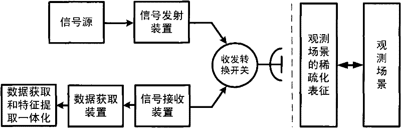
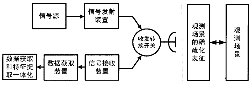
[0071] Specific embodiment one: time-sparse based sparse microwave imaging method (see figure 1 )

[0072] In sparse microwave imaging, there is a scene X with obvious sparseness, that is to say, there are few non-zero elements in X or most of the elements are much greater than zero. For a scene with N elements and obvious sparseness:

[0073] ||X|| 0 <

[0074] where ||X|| p , which represents the p-norm of X.

[0075] In sparse microwave imaging, although the observed scene is not obviously sparse, it often has a strong correlation, and there is information redundancy, so it is also sparse. We denote the observation scene as X, which has a sparse domain, that is to say, it has a sparse transformation matrix Ψ, such that

[0076] X=Ψ·α

[0077] ||α|| 0 <

[0078] The sparse coefficient vector α is called the sparse representation of X, and it is a vector with few non-zero elements. The transformation corresponding to this sparse change matrix can be unit transfor...

specific Embodiment 2

[0124] Specific embodiment 2: Sparse microwave imaging based on joint sparsity of time and space

[0125] Step 1-Step 4: Use the same method as in Embodiment 1 to obtain the echo data of multiple channels Step S5, according to Step 1-Step 4, the echo sampling formula can be obtained

[0126] Y=ФX+N

[0127] The above formula describes the method of obtaining observations during time-sparse sampling, and the following analyzes the joint time-sparse and space-sparse signal acquisition methods and processing methods. Consider a sparse microwave imaging system with a total of I sampling apertures (spaces). The data acquisition equation of each sampling aperture is

[0128] T i =Ф i X+N i i=1,...,I

[0129] Among them, Y i , Ф i and N i are the observation quantity, observation matrix and observation noise of the i-th aperture, respectively. All sampling points can be expressed as a new vector

[0130] Y ′ = ...


PUM


Abstract

The invention discloses a sparse microwave imaging method, relating to the information acquisition and processing technology. By utilizing sparsity of microwave imaging observation, through introducing sparse signal processing theory into microwave imaging technology, after signal processing and information extraction, the geometrical and physical characteristics of an observation object such as space position, scattering characteristic and motion characteristic and the like are obtained, wherein the sparse signal processing theory is through searching sparse representation field of the observation object, obtaining sparse microwave signal of the observation object in space, time, frequency spectrum or polarizing field sparse sampling. According to the sparse microwave imaging method in the invention, the bottleneck problems existed in the prior art such as difficult system realization, complex imaging processing method, redundant information and difficult feature extraction and the like based on Nyquist sampling theorem and classic digital signal processing theory are solved, thus microwave imaging system structure and imaging complexity is reduced.

Description

technical field [0001] The invention relates to the technical field of information acquisition and processing, and is a sparse microwave imaging method, which uses microwave imaging to observe the sparsity of a scene data set, combines the observed scene sparsity when transmitting signals, and uses antennas to obtain data lower than Nayquil Data sampling based on the Steer's theorem realizes the integration of imaging and information extraction during signal processing. Background technique [0002] Microwave imaging technology uses electromagnetic waves in the microwave spectrum as a detection method, and uses microwave imaging sensors to obtain the scattering characteristics and related information of the observed object. Compared with optical imaging technology, microwave imaging is not limited by sunlight and weather conditions, and has the ability to observe targets or scenes all-weather and all-weather. It has developed into an important means of remote sensing applica...

Claims


Application Information

Patent Timeline
IPC IPC(8): G01S13/90G01S7/41
Inventor 吴一戎洪文张冰尘王彦平李道京
Owner INST OF ELECTRONICS CHINESE ACAD OF SCI
Why Eureka
Try Eureka