Indirectly heated fluidized bed dryer

A fluidized bed drying and indirect technology, which is applied in indirect heat exchangers, fluidized bed heat exchangers, heating to dry solid materials, etc., can solve the problems of the dryer shell not being kept constant and hydrodynamic interference, etc., to achieve Reduce speed increase, improve heat conduction effect

Inactive Publication Date: 2013-10-02
RWE POWER AKTIENGESELSCHAFT
View PDF6 Cites 0 Cited by
  • Summary
  • Abstract
  • Description
  • Claims
  • Application Information

AI Technical Summary

Problems solved by technology

However, the solution of EP0341347A1 has the disadvantage that the cross-sectional area of ​​the dryer housing does not remain constant in the region of the heat exchanger inserts at its height
This will cause disturbances in the hydrodynamics in the fluidized bed, which is undesirable for power optimization reasons

Method used


Image

  • Indirectly heated fluidized bed dryer
  • Indirectly heated fluidized bed dryer

Examples


Embodiment Construction

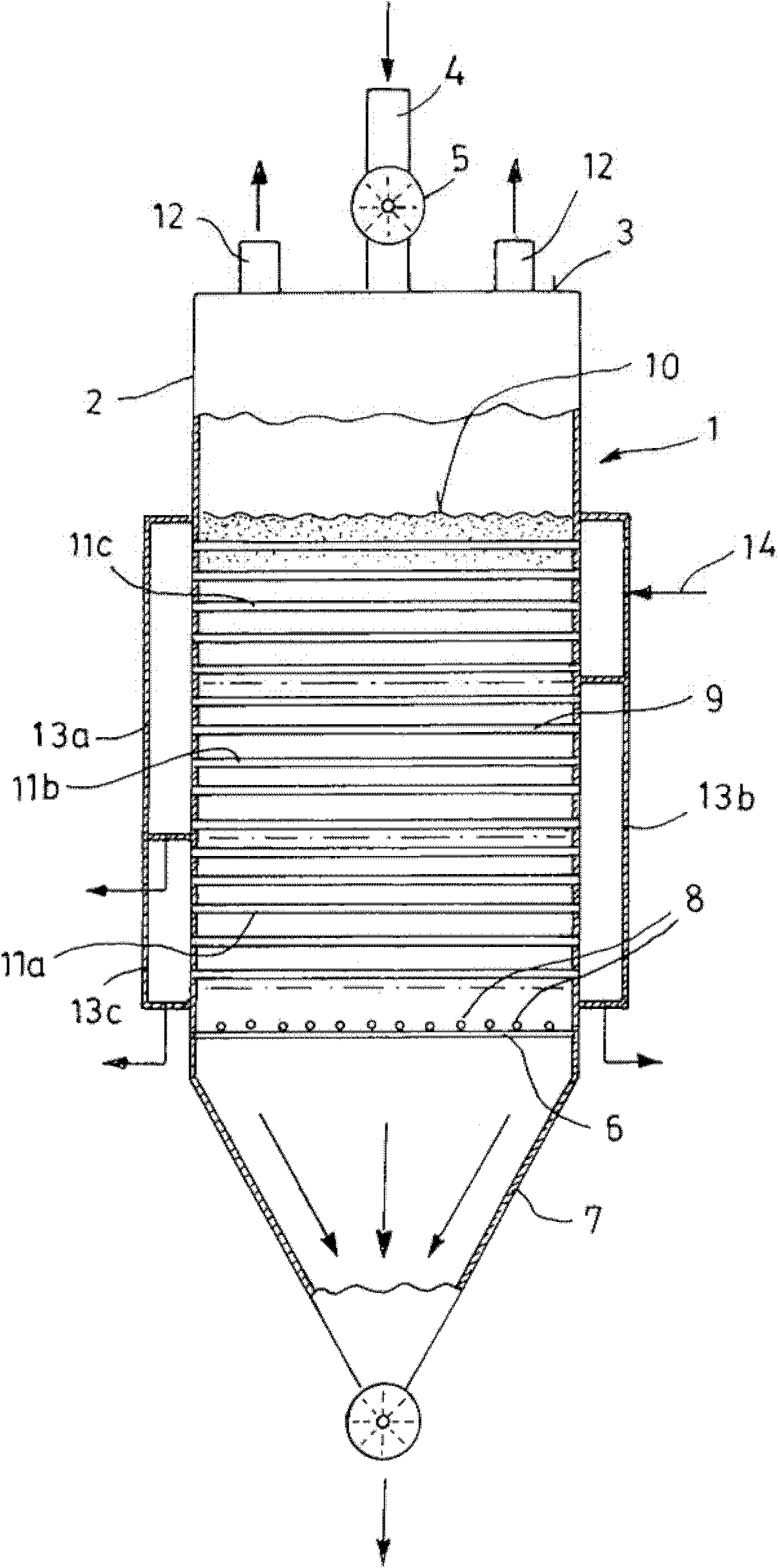
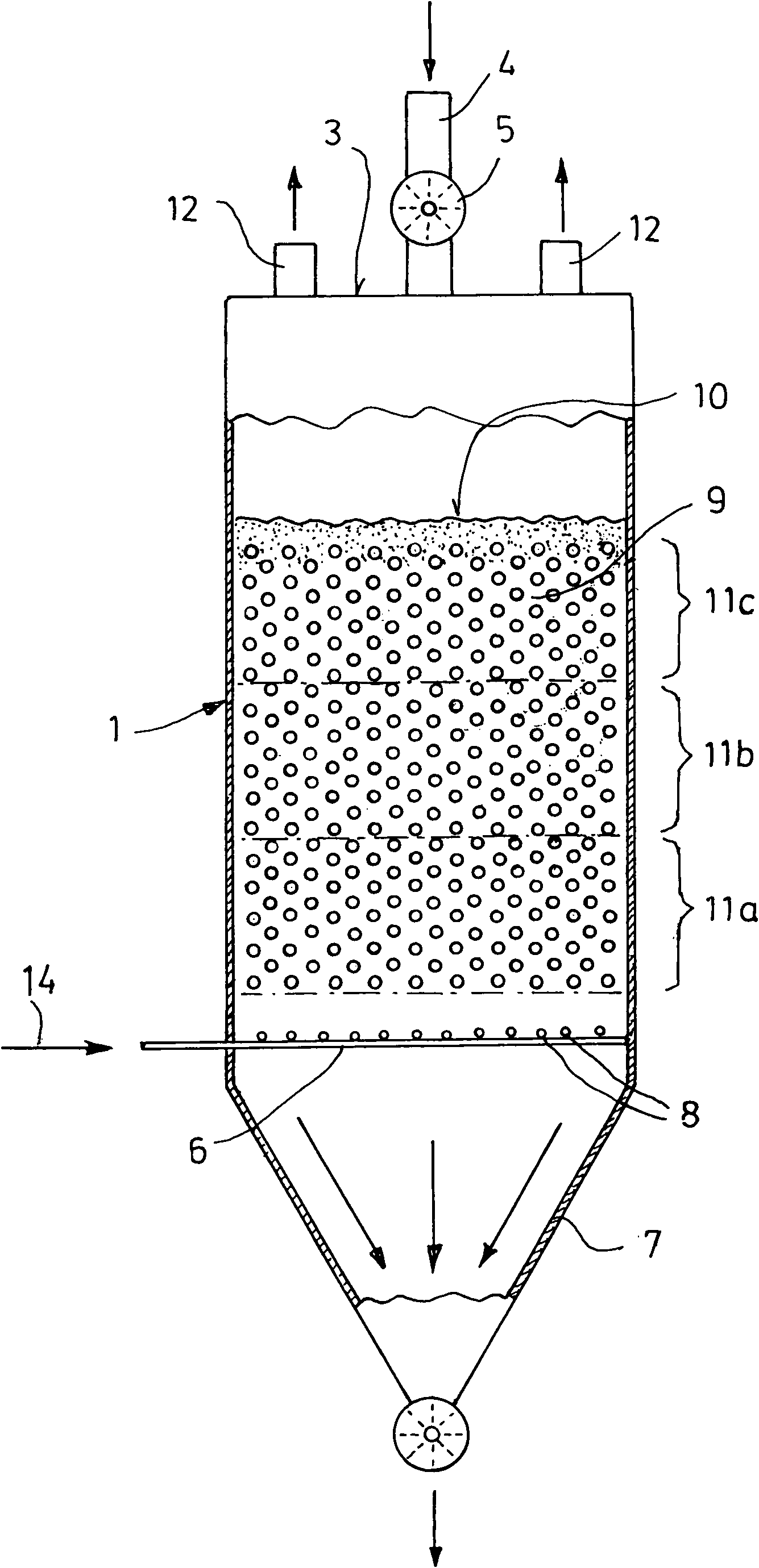
[0028] figure 1 The fluidized bed dryer 1 shown has a housing 2 with a rectangular cross section. On the upper end surface 3 of the fluidized bed dryer 1, a filling pipe 4 with a honeycomb wheel gate 5 is arranged as a raw lignite feeding device. On the lower end of the fluidized bed dryer 1 away from the upper end surface 3, a funnel-shaped outlet 7 is arranged below the aerated bottom 6, and a mechanical discharge device such as a honeycomb wheel gate 5 is arranged on the lower end of the outlet. There, too, a screw conveyor or the like can be used as a mechanical discharge device instead of the honeycomb wheel gate. In this embodiment, the fluidized bed dryer 1 is mainly used for drying lignite and is described with reference to a method for drying lignite. However, the invention should be understood that the dryer can also be used for drying other particulate matter.

[0029] The aerated bottom 6 is provided on its side facing away from the discharge 7 with nozzles 8 fo...


PUM


Abstract

The invention relates to an indirectly heated fluidized bed dryer (1) for drying moist fine-grained bulk material. The fluidized bed dryer (1) comprises a housing (2) with an aerated bottom (6), heat exchanger inners extending above the aerated bottom (6) and at least one (6) The lower discharge device for the dried loose material. The fluidized bed dryer (1) according to the invention is characterized in that the available flow cross section of the housing (2) in the region of the heat exchanger inserts is constant over the entire height of the heat exchanger inserts in the cross section of the housing The case increases in the flow direction of the fluidized medium. Inadmissible expansion of the steady-state fluidized bed is reliably prevented in this way.

Description

technical field [0001] The invention relates to an indirectly heated fluidized bed dryer for drying moist fine-grained bulk material such as lignite, the fluidized bed dryer comprising a housing with an aerated bottom, above the aerated bottom Extended heat exchanger insert and at least one discharge device for dried bulk material arranged below the aerated bottom, the available flow cross-section of the housing in the region of the heat exchanger insert The overall height of the piece increases in the flow direction of the fluidizing gas. Background technique [0002] Such a fluidized bed dryer is disclosed, for example, in EP0341347A1. [0003] When processing lignite into boiler coal for combustion in steam generators, it is known to simultaneously pulverize and grind lignite (grinding dry) in impact mills and hammer mills that are components of power plant boilers, Wherein, the drying energy required for drying is provided by the branched flue gas flow. [0004] As th...

Claims


Application Information

Patent Timeline
Patent Type & Authority Patents(China)
IPC IPC(8): F26B3/084
CPCF26B3/084F28D13/00
Inventor H-J·克卢茨C·莫泽
Owner RWE POWER AKTIENGESELSCHAFT
Why Eureka
Try Eureka