Welding robot

A welding robot and reducer technology, applied in the field of robots, can solve the problems of unfavorable operators for real-time observation and operation, small work space, limited welding work space, etc.

Inactive Publication Date: 2011-10-26
DALIAN JIAOTONG UNIVERSITY
View PDF9 Cites 30 Cited by
  • Summary
  • Abstract
  • Description
  • Claims
  • Application Information

AI Technical Summary

Problems solved by technology

[0002] At present, welding robots mostly use three-jaw or four-jaw chucks for clamping. When clamping on the welded pipe, the heat generated by welding is easily transmitted to the chuck, causing it to be stuck due to thermal deformation, making it difficult to disassemble the chuck; The welding space of the tube-type welding robot is severely limited in the welding where the nozzles are closely distributed. At the same time, due to the installation method of the tube-type welding robot, the operating space left for the operator is very smal

Method used


Image

  • Welding robot
  • Welding robot
  • Welding robot

Examples


Embodiment Construction

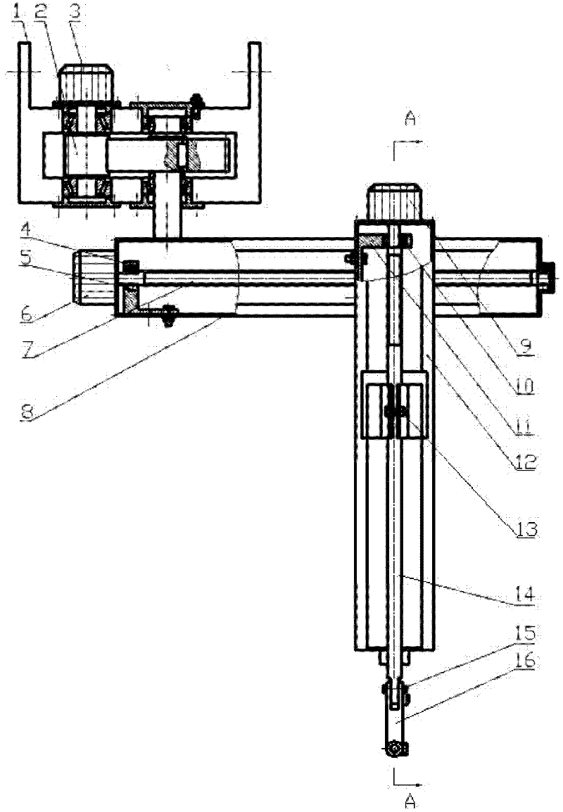
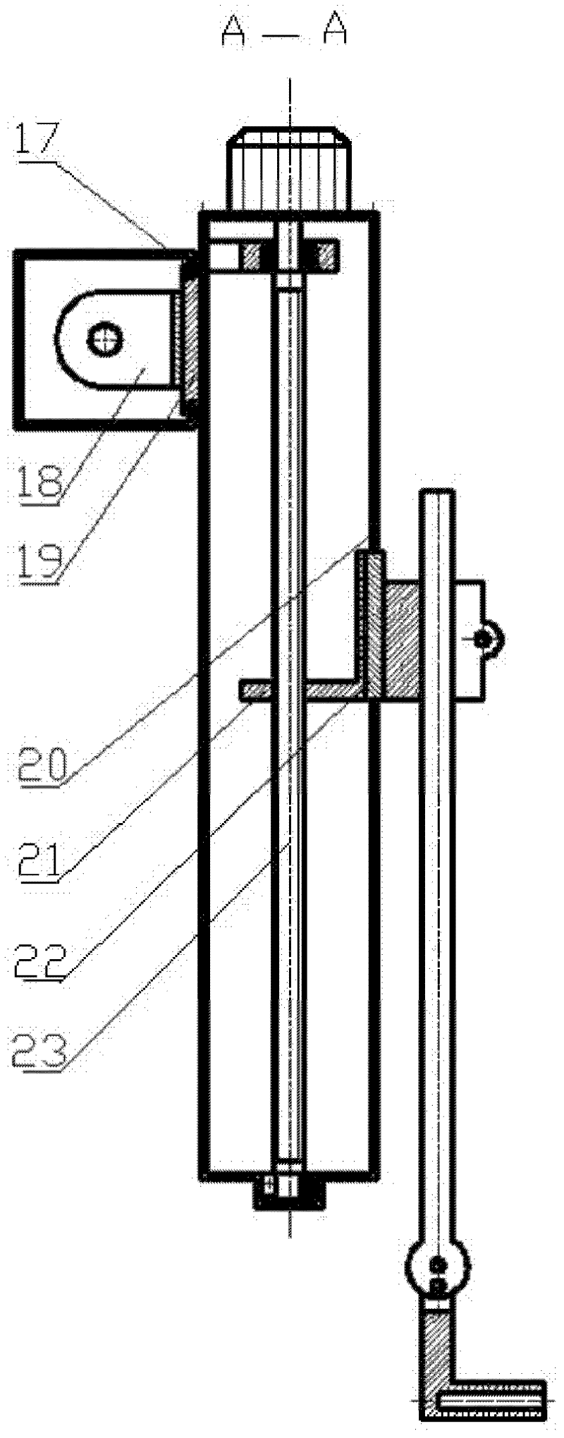
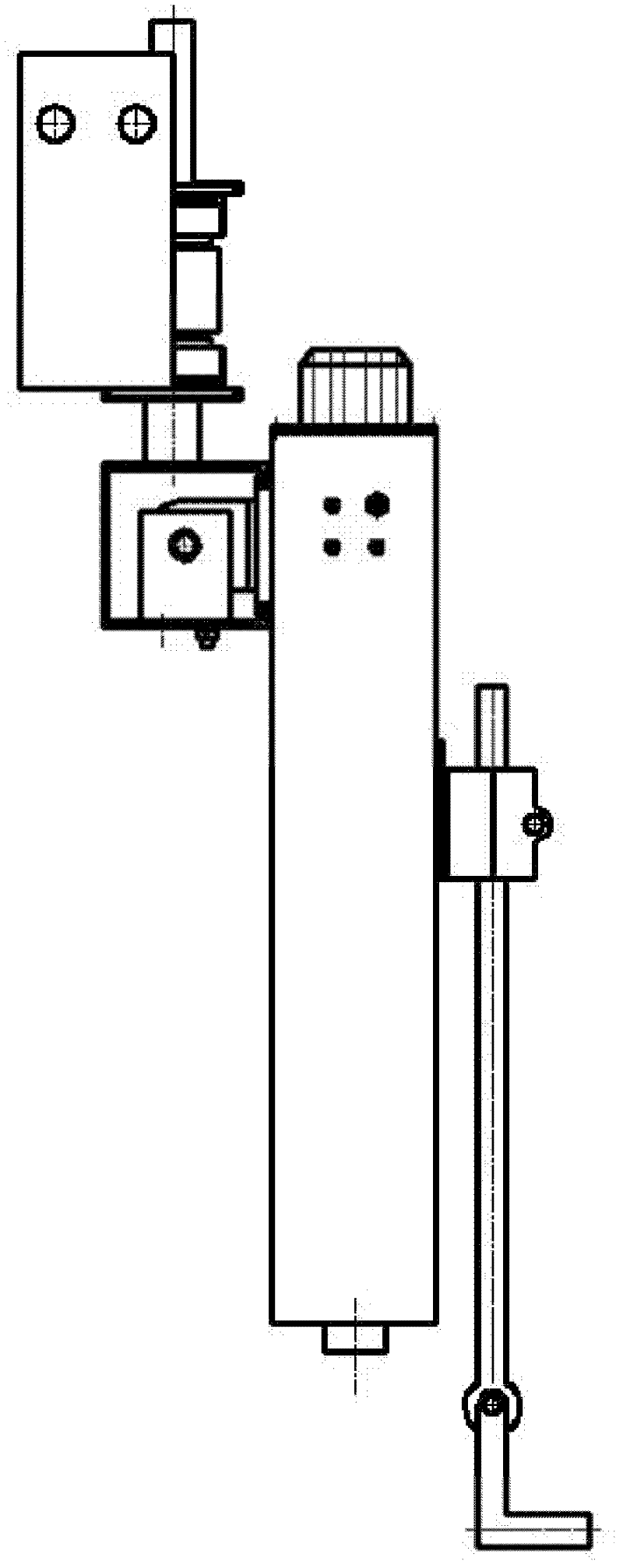
[0019] Such as figure 1 , 2 , A kind of welding robot shown in 3, 4, comprises installation frame 1, speed reducer 2, arm motor 3, bearing I 4, support I 5, traverse motor 6, traverse lead screw 7, traverse arm 8, Vertical movement motor 9, bearing II10, support II11, vertical movement arm 12, fastening frame 13, welding torch rod 14, welding torch angle regulator 15, welding torch 16, transverse movement guide rail 17, transverse movement nut 18, transverse movement slider 19, Vertically moving guide rail 20, vertically moving nut 21, vertically moving slide block 22, vertically moving leading screw 23. The installation frame 1 can be hung on the wall through the installation hole for use. A reducer 2 is fixed on the installation frame 1, and the rotating arm motor 3 is fixed on the end cover of the reducer, which drives the input shaft of the reducer 2 to rotate, and after being decelerated by the reduction gear, its output shaft drives the traverse arm 8 to swing; A pai...


PUM


Abstract

The invention provides a welding robot is disclosed. A speed reducer is fixed to a mounting frame. A tumbler motor drives the input shaft of the speed reducer to rotate; and after the speed is reduced, the output shaft of the speed reducer drives a transverse moving arm to swing. A transverse moving lead screw supported by a bearing I is fixed in the transverse moving arm. A transverse moving motor drives the transverse moving lead screw to rotate, thus driving a transverse moving nut and a vertical moving arm to transversely move along a transverse moving guide rail on the transverse moving arm through transverse moving sliders. A vertical moving lead screw supported by a bearing II is fixed in the vertical moving arm. A vertical moving motor drives a vertical moving lead screw to rotate so as to drive a vertical moving nut and a fastening frame to vertically move along a vertical moving guide rail on the vertical moving arm through vertical moving sliders. The fastening frame is fixedly connected to a welding gun bar which is connected to a welding gun through a welding gun angle regulator. Besides, a welding rod is mounted in the welding gun. The welding robot has the following major advantages: the welding robot is capable of carrying out oscillation within a horizontal plane, movement in radius and movement in a vertical plane; the angle of inclination of the welding gun can be adjusted by the welding gun angle regulator; and automatic welding in a narrow or dangerous environment is realized.

Description

technical field [0001] The invention relates to a robot used in the field of welding, especially suitable for realizing automatic welding in narrow or dangerous environments, and belongs to an automatic control welding robot. Background technique [0002] At present, welding robots mostly use three-jaw or four-jaw chucks for clamping. When clamping on the welded pipe, the heat generated by welding is easily transmitted to the chuck, causing it to be stuck due to thermal deformation, making it difficult to disassemble the chuck; The welding space of the tube-type welding robot is severely limited in the welding where the nozzles are closely distributed. At the same time, due to the installation method of the tube-type welding robot, the operating space left for the operator is very small, which is not conducive to the real-time operation of the operator. Observation and operation; It is difficult to realize the chucking of the pipe welding robot using the three-jaw or four-ja...

Claims


Application Information

Patent Timeline
IPC IPC(8): B23K37/02
Inventor 邵万珍吴国奇于可衍边海瑞
Owner DALIAN JIAOTONG UNIVERSITY
Why Eureka
Try Eureka