Stress-relieving device for seamless rails by using vibration method

A seamless steel rail and stress relief technology, which is applied in the direction of track, track laying, track maintenance, etc., can solve the problems of the overall weight of the impact equipment, large impact force, inaccurate measurement results, etc., to achieve real-time monitoring, improve impact efficiency, Measuring Precise Effects

Inactive Publication Date: 2011-10-26
HUBEI UNIV OF TECH
View PDF5 Cites 16 Cited by
  • Summary
  • Abstract
  • Description
  • Claims
  • Application Information

AI Technical Summary

Problems solved by technology

[0002] Seamless track is currently the main track structure commonly used in railways at home and abroad. It is generally used in railway construction. The current construction technology for laying seamless lines at one time mainly includes single sleeper, group sleeper and long rail row. There are three catch methods, among which the single sleeper laying method cancels the traditional rail row assembly base, and the long steel rails and sleepers are directly transported to the construction site for laying. Its comprehensive operation efficiency is high, the technology is advanced, practical and reliable. Leading level, but for a long time, in the process of laying and maintaining seamless lines, the stress relief method and technology are still relatively backward. Based on the current situation and development trend of my country's railway construction, more efficient new stress relief methods and equipment are urgently needed further research
In order to ensure the rigidity and straightness of the seamless line rail, the current method of stretching the rail is mainly the mechanical method of manual traction, which uses high-strength bolts, gusset fasteners or elastic fasteners to constrain the rail, One end of a 500m-long steel rail is fixed, and 400t of tension is applied to the other end to stretch the rail to generate tensile stress inside the rail. The distribution situation is not conducive to the uniform release of the stress of the rail; on the other

Method used


Image

  • Stress-relieving device for seamless rails by using vibration method
  • Stress-relieving device for seamless rails by using vibration method
  • Stress-relieving device for seamless rails by using vibration method

Examples


Embodiment Construction

[0023] Markings in the attached drawings:

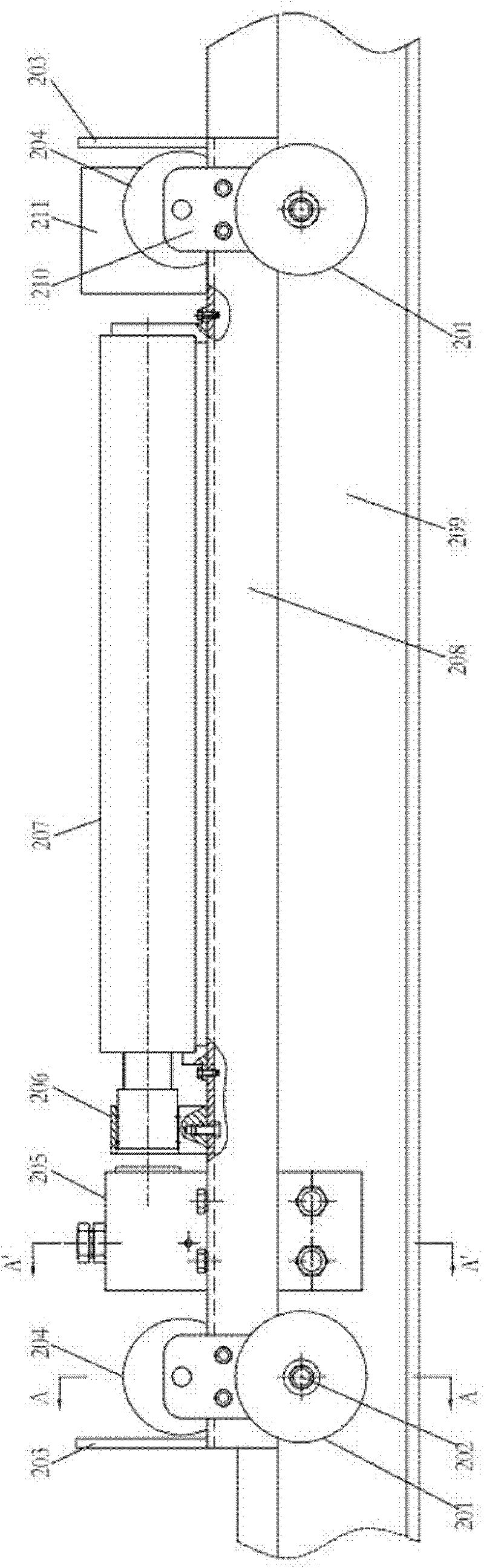
[0024] attached figure 1 , 201—hauling wheel, 202—anti-covering wheel shaft, 203—handle, 204—traveling wheel, 205—clamp body, 206—guiding support block, 207—impact gas-hydraulic booster cylinder, 208—channel steel, 209— Rail, 210—rely on cladding plate, 211—side plate.

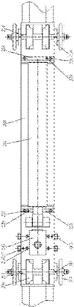
[0025] attached figure 2Among them, 214—walking axle, 216—bolt, 217—pin, 220—pin, 221—bolt, 228—fixed plate, 310—positioning hole, 603—bolt.

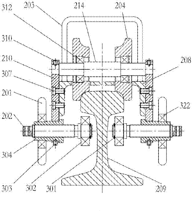
[0026] attached image 3 , attached Figure 4 Among them, 301—circlip, 302—anti-covering wheel, 303—locating pin, 304—anti-covering wheel axle sleeve, 307—bolt, 312—traveling wheel bearing, 322—hauling wheel bearing.

[0027] attached Figure 5 In, 401—impact rod, 402—flange, 406—oil chamber, 408—oil chamber, 409—piston, 410—air pressure chamber, 411—flange with holes, 412—air pressure chamber, 413—piston rod, 414—air pressure chamber, 415—flange with holes, 416—air pressure chamber, 417—base flange, 418—air hole, 420—...


PUM


Abstract

The invention discloses a stress-relieving device for seamless rails by using a vibration method, and is implemented by carrying out field detection on the stress-relieving effect of rails mainly by using a device for realizing the stress homogenization of rails in a periodic-vibration gas-liquid pressurized mode and supplementarily by using a stress sensor, and then carrying out stress-relieving operation in a machine-liquid-electricity integrated automatic mode. The whole stress-relieving device disclosed by the invention is light in weight, and provided with an anti-overturn device for ensuring a trolley is not overturned to the side during the operation of the trolley, thereby reducing the labor intensity and improving the operating efficiency and quality.

Description

technical field [0001] The invention relates to a stress relieving device of a seamless rail by exciting vibration method, specifically for the seamless rail, adopting a periodic vibration method to realize stress relieving, and belongs to the field of special mechanical products for stress relieving of seamless rails in the railway industry. Background technique [0002] Seamless track is currently the main track structure commonly used in railways at home and abroad. It is generally used in railway construction. The current construction technology for laying seamless lines at one time mainly includes single sleeper, group sleeper and long rail row. There are three catch methods, among which the single sleeper laying method cancels the traditional rail row assembly base, and the long steel rails and sleepers are directly transported to the construction site for laying. Its comprehensive operation efficiency is high, the technology is advanced, practical and reliable. Leading ...

Claims


Application Information

Patent Timeline
IPC IPC(8): E01B31/02E01B29/00
Inventor 陈水胜华中平余娟周现柳王鹿婷梁亚茹李茂陈志成
Owner HUBEI UNIV OF TECH
Why Eureka
Try Eureka