Engine-driven cascade heat pump device

An engine-driven, heat pump device technology, applied in superheaters, refrigerators, compressors, etc., can solve problems such as complex systems, high initial investment, and easy failures, achieve clean and comfortable conditions, overcome low efficiency, and improve The effect of energy efficiency

Inactive Publication Date: 2011-10-26
YANTAI UNIV
View PDF7 Cites 13 Cited by
  • Summary
  • Abstract
  • Description
  • Claims
  • Application Information

AI Technical Summary

Problems solved by technology

Its disadvantages are that due to the low outlet water or air temperature, generally lower than 60°C, it is mostly used in conjunction with fan coil units, the system is complex and the initial investment is high; The third is that the outlet water temperature of ordinary heat pumps is generally low, and it cannot be combined with the end radiators commonly used in the north for heating. The efficiency is very low and it is prone to failure; Fourth, most of the existing heat pumps are electric. Since coal power generation still accounts for a considerable proportion in my country's power structure, the large amount of power consumed by the heat pump not only causes power load peak-valley difference and other power supply It also indirectly caused the emission of a large amount of greenhouse gases and pollutants, aggravating the greenhouse effect and environmental pollution

Method used


Image

  • Engine-driven cascade heat pump device
  • Engine-driven cascade heat pump device
  • Engine-driven cascade heat pump device

Examples


Embodiment 1

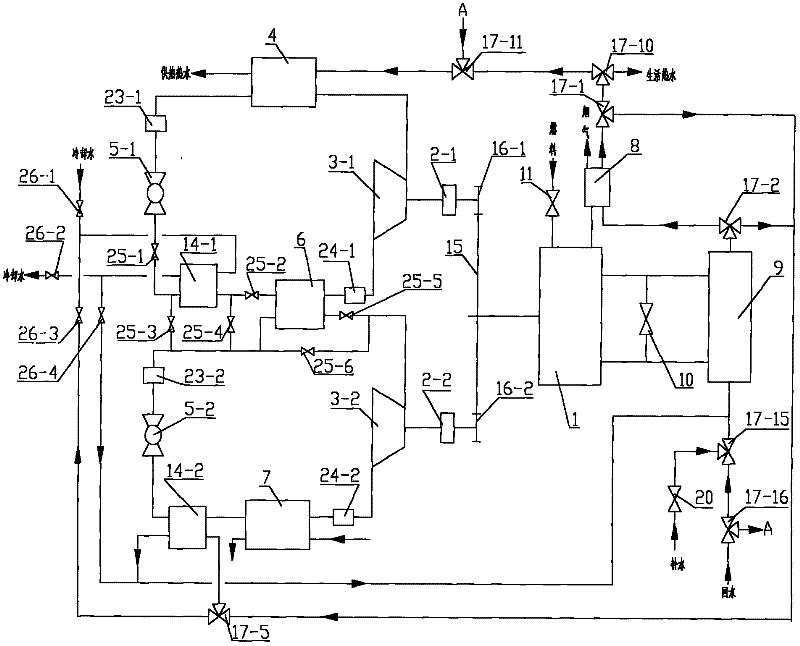
[0023] Embodiment 1: as Figure 1a As shown, a binary cascade heat pump device in which one engine drives two compressors consists of three parts: a binary cascade heat pump system, an engine system and a water circuit. As shown in 1a, a binary cascade heat pump system in which one engine drives two compressors includes a high-temperature stage circulation system and a low-temperature stage circulation system. High temperature stage compressor 3-1, condenser 4, high temperature stage liquid receiver 23-1, high temperature stage throttle valve 5-1, high temperature stage refrigerant heater 14-1, condensation evaporator 6, high temperature stage gas-liquid separation 24-1, the first refrigerant side valve 25-1, and the second refrigerant side valve 25-2 form a high-temperature stage refrigerant circulation system, the high-temperature stage compressor 3-1 is connected to the condenser 4, and the condenser 4 is connected to the high-temperature stage The liquid storage device 23-...

Embodiment 2

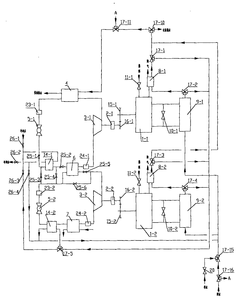
[0026] Embodiment 2: as Figure 1bAs shown, the binary cascade heat pump device with two engines driving two compressors consists of three parts: the binary cascade heat pump system, the engine system and the water circuit. The binary cascade heat pump system and its refrigeration and heating operation principles are basically the same as those in Embodiment 1, the difference is that the two compressors 3-1 and 3-2 of the system are respectively driven by two engines 1-1 and 1-2 . The engine system consists of engines 1-1, 1-2, engine cooling heat exchangers 9-1, 9-2, flue gas heat exchangers 8-1, 8-2, cooling water bypass valves 10-1, 10-2 , Composed of fuel regulating valves 11-1 and 11-2. The engine 1-1 is connected to the engine cooling heat exchanger 9-1, a cooling water bypass valve 10-1 is provided between the engine 1-1 and the engine cooling heat exchanger 9-1, and the engine cooling heat exchanger 9-1 is connected to the smoke The gas heat exchanger 8-1 and the fl...

Embodiment 3

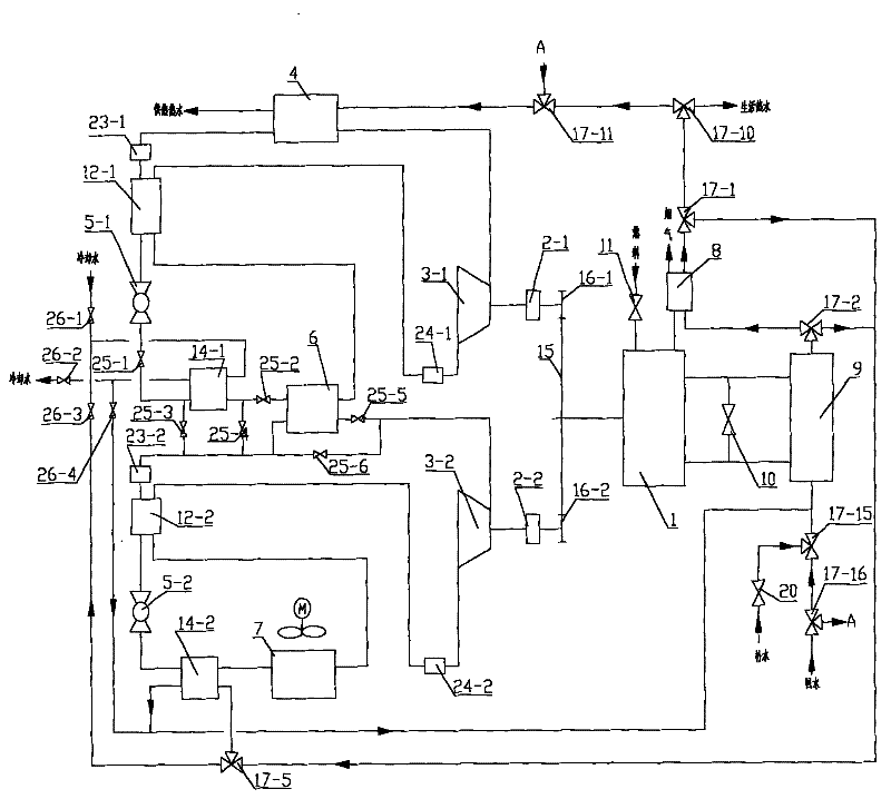
[0027] Embodiment 3: as Figure 2a As shown, it is basically the same as Embodiment 1, the difference is that the high and low temperature recuperation heat exchangers 12-1 and 12-2 are added in the binary cascade heat pump system. The high-temperature stage liquid receiver 23-1 and the high-temperature stage throttle valve 5-1 and the high-temperature stage gas-liquid separator 24-1 and the condensing evaporator 6 are connected with a high-temperature stage regenerative heat exchanger 12-1, and a low-temperature stage The low-temperature stage recuperation heat exchanger 12-2 is connected between the liquid reservoir 23-2 and the low-temperature stage throttle valve 5-2 and between the low-temperature stage gas-liquid separator 24-2 and the evaporator 7; cold evaporator.

[0028] When the system is in refrigeration operation, the high-temperature compressor does not operate, the clutch 2-1 is disconnected, the high-temperature refrigerant heater 14-1 is used as a condenser, ...


PUM


Abstract

The invention discloses an engine-driven cascade heat pump device which is characterized by comprising a cascade heat pump system, at least an engine system and a water loop, wherein the cascade heat pump system comprises a high-temperature circulating system and a low-temperature circulating system; a high-temperature compressor, a condenser, a high-temperature reservoir, a high-temperature throttling valve, a high-temperature refrigerant heater, a condensation evaporator, a high-temperature air-liquid separator and a refrigerant side valve form a high-temperature refrigerant circulating system; a low-temperature compressor, a condensation evaporator, a low-temperature reservoir, a low-temperature throttling valve, a low-temperature refrigerant heater, an evaporator, a low-temperature air-liquid separator and a refrigerant side valve form a low-temperature refrigerant circulating system; and the engine system comprises an engine, an engine cooling heat exchanger, a smoke heat exchanger, a cooling water bypass valve and a fuel regulating valve. The engine-driven cascade heat pump device disclosed by the invention can improve the utilization efficiency of fuel, realize high-efficiency utilization of energy sources, reducing pollution, and realizing multiple functions of refrigerating in summer, heating in winter, preparing domestic hot water and the like with the same unit.

Description

Technical field: [0001] The invention relates to an engine-driven cascade heat pump device, which belongs to the technical field of heat pump utilization. Background technique: [0002] At present, the heating and heating of buildings in our country mainly include boiler room or thermal power plant heating, heat pump heating and other methods. Boiler rooms or thermal power plants mostly rely on direct combustion of fossil fuels to obtain heat. This heating method not only consumes a large amount of non-renewable energy, but also emits a large amount of greenhouse gases and pollutants, causing serious environmental pollution. Heat pump heating is widely used in southern my country. Its disadvantages are that due to the low outlet water or air temperature, generally lower than 60°C, it is mostly used in conjunction with fan coil units, the system is complex and the initial investment is high; The third is that the outlet water temperature of ordinary heat pumps is generally l...

Claims


Application Information

Patent Timeline
Patent Type & Authority Applications(China)
IPC IPC(8): F25B7/00F25B40/06
Inventor 赵海波吴坤
Owner YANTAI UNIV
Why Eureka
Try Eureka