

End mill
A technology of end milling cutter and base end, which is applied in the direction of milling cutter, reamer, cutter for milling machine, etc. It can solve the problems such as difficult cutting for a long time, and achieve the effects of reducing frictional heat, suppressing vibration, and suppressing interlayer peeling
- Summary
- Abstract
- Description
- Claims
- Application Information
AI Technical Summary
Problems solved by technology
Method used
Image

Examples
Embodiment 1)
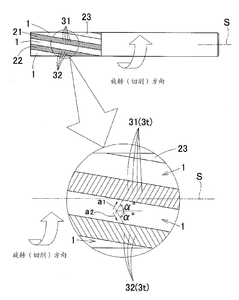
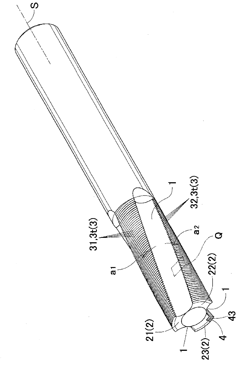
[0079] In the end mill of Example 1, in figure 1 represents a stereogram, and in addition, in figure 2 and image 3 The figure in the middle shows the structure explanatory drawing of the periphery of the spiral groove 1 and the land 2 when viewed from the front-end side of a blade part (front view), and when viewed from the side (side view). and, in Figure 4 , which shows an enlarged explanatory view of a section in the torsional direction of the first notch of the first land 21, and, in Figure 5 3 shows a perspective view of the diamond sintered state before the helical groove 1 or notch 3 is engraved in the manufacturing process of the end mill of the present invention.
[0080] In the end mill of Example 1, three spirals are formed at approximately equal intervals at a central phase interval of 120 degrees (in this case, the phase interval at the central position of each groove width 1w) around the rotation axis on the front end side. Groove 1, thus, a total of thre...
Embodiment 2)
[0092] To the end mill of embodiment 2, in Figure 6 represents a stereogram, and in addition, in Figure 7 and Figure 8 In , explanatory diagrams showing the structure of the spiral groove 1 and the land 2 when viewed from the front end side of the blade portion (front view) and when viewed from the side (side view). Figure 9 It is a perspective view of the sintered body 42 in the manufacturing process.
[0093] In the end mill of Example 2, five spiral grooves 1 are formed at approximately equal intervals at a center phase interval of 70 to 74 degrees (phase interval at the center position of each groove width 1w) centered on the rotation axis on the front end side. Here, a total of five lands 2 consisting of one land group and three remaining lands 23 are formed at unequal positions in which adjacent intervals are slightly increased or decreased. And, the first of the three margins 2 is used as the first margin 21, the second is used as the second margin 22, and the th...
Embodiment 3)
[0101] Regarding the end mill of Example 3, in Figure 10 The figure in the figure shows the structure explanatory drawing of the periphery of the helical groove 1 and the land 2 seen from the front-end|tip side of a blade part.
[0102] In the end mill of Example 3, five helical grooves 1 are formed at approximately equal intervals at a center phase interval of 70° to 74° (phase interval at the center position of each groove width 1w) around the rotation axis on the front end side. Thus, a total of five margins 2 consisting of two margin groups A and B and one remaining margin 23 are formed at unequal positions with slightly increased or decreased adjacent intervals. The first of the five margins 2 in total is the first margin 21 of the first group, the second is the second margin 22 of the first group, and the third is the first margin of the second group. As for the bands 21 , the fourth one is used as the second margin 22 of the second group, and the fifth one is used as ...
PUM
 Abstract
Description
Claims
Application Information