Die box gradient lifting type continuous building block forming machine
A lifting type and forming machine technology, which is applied in the direction of ceramic forming machines, unloading devices, manufacturing tools, etc., can solve the problems of short vibration, unfavorable stability and safety, beautiful and uniform, uneven block structure density, etc., and achieve tight and precise operation coordination , Save labor resources, easy to operate and maintain
- Summary
- Abstract
- Description
- Claims
- Application Information
AI Technical Summary
Problems solved by technology
Method used
Image

Examples
Embodiment Construction
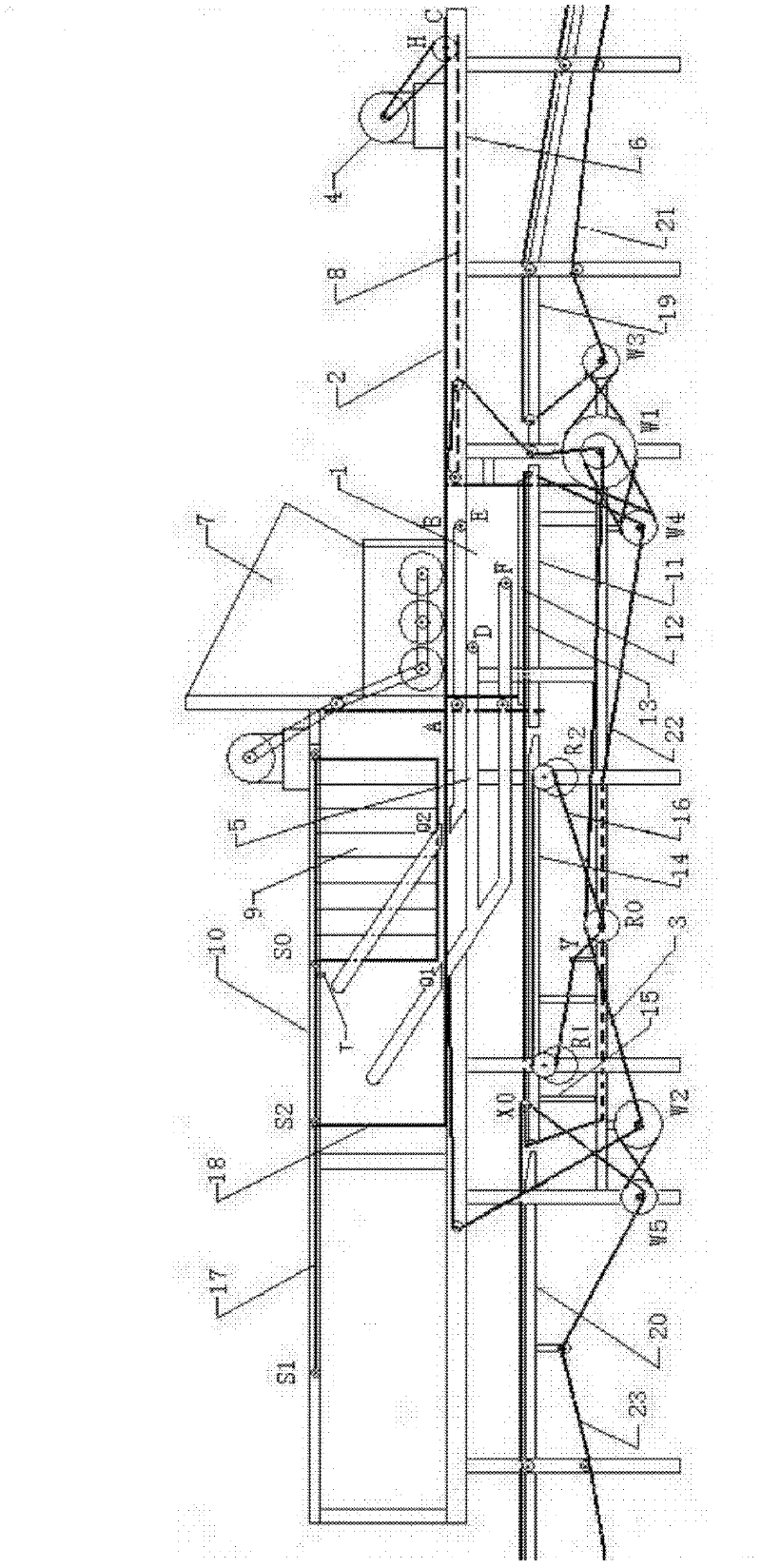
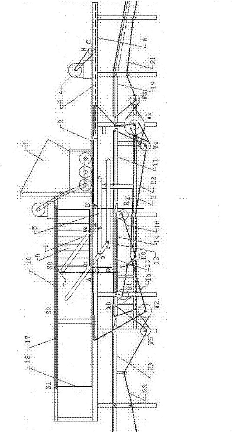
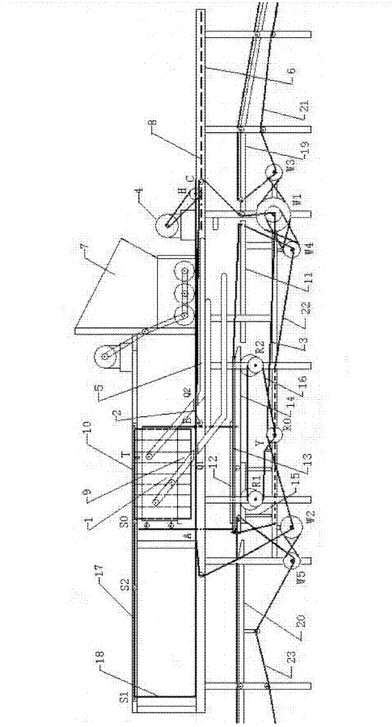
[0033] Before starting, the combination of formwork-formwork box system and platen head is generally in the state shown in Figure 2. At this time, the plate surface BC of formwork 2 is still under the position of hopper box 7 with coagulation slurry and the bottom discharge is blocked. mouth, its left end vertical rod 18 is close to the left end S1 point of the platen head connecting rod 17; the mold box 1 carries the vibrating pallet 13 on the platform 14, and its side pulleys D, E, F are on the slope of the track groove 5 and tend to move horizontally to the right. , the mold core platen head 9 is limited by the elastic resistance head T and is positioned at the rightmost end of the side beam 10, facing the mold box 1 through the air; the empty pallets 12 are tiled on the platform 19 in turn.
[0034] Turn on the power 4, make it run clockwise to drive the gear H to slide to the right along the track groove 8, impel the mold base 2 to carry the mold box 1 and the vibration su...
PUM
 Abstract
Description
Claims
Application Information
 - R&D
- Intellectual Property
- Life Sciences
- Materials
- Tech Scout
- Unparalleled Data Quality
- Higher Quality Content
- 60% Fewer Hallucinations
Browse by: Latest US Patents, China's latest patents, Technical Efficacy Thesaurus, Application Domain, Technology Topic, Popular Technical Reports.
© 2025 PatSnap. All rights reserved.Legal|Privacy policy|Modern Slavery Act Transparency Statement|Sitemap|About US| Contact US: help@patsnap.com