Optical signal to noise ratio detection method and device

A signal-to-noise ratio and light detection technology, applied in the field of optical communication, can solve the problems of slow detection speed, high detection cost, long time-consuming OSNR, etc., and achieve the effect of improving speed and efficiency

Inactive Publication Date: 2011-11-02
江苏尚莱特医药化工材料有限公司
View PDF3 Cites 21 Cited by
  • Summary
  • Abstract
  • Description
  • Claims
  • Application Information

AI Technical Summary

Problems solved by technology

[0005] However, there are the following disadvantages in the prior art: when performing OSNR detection, it is necessary to use an expensive polarization controller to continuously adjust the polarization state of the optical signal in order to find a polarization state so that the light intensity output by the two arms of the polarization beam splitter Just one is the maximum value and the other is the minimum value, the detection cost is high, and the detection speed is slow; when detecting the OSNR of the DWDM signal, it is necessary to perform OSNR detection on all channels, and the signal polarization state of each channel is different. When the OSNR detection of one channel is ended and the OSNR corresponding to another channel is detected, the polarization controller needs to be continuously adjusted to find a polarization state again so that the light intensity output by the two arms of the polarization beam splitter just reaches the maximum value and the other reaches the maximum value. Minimum value, resulting in long time-consuming, slow speed and low efficiency after detecting the OSNR corresponding to all channels

Method used


Image

  • Optical signal to noise ratio detection method and device
  • Optical signal to noise ratio detection method and device
  • Optical signal to noise ratio detection method and device

Examples


Embodiment Construction

[0027] The following will clearly and completely describe the technical solutions in the embodiments of the present invention with reference to the accompanying drawings in the embodiments of the present invention. Obviously, the described embodiments are only some, not all, embodiments of the present invention. Based on the embodiments of the present invention, all other embodiments obtained by persons of ordinary skill in the art without creative efforts fall within the protection scope of the present invention.

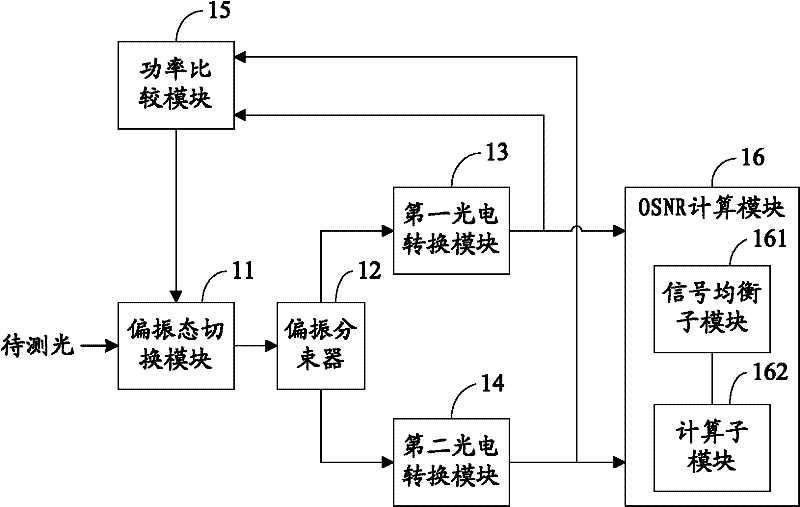
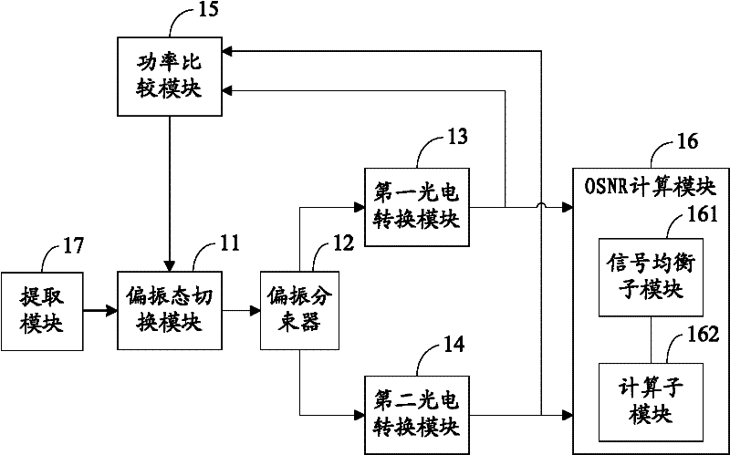
[0028] An embodiment of the present invention provides a device for detecting optical signal-to-noise ratio OSNR, the structure of which is as follows figure 1 As mentioned above, the device includes: a polarization switching module 11 , a polarization beam splitter 12 , a first photoelectric conversion module 13 , a second photoelectric conversion module 14 , a power comparison module 15 and an OSNR calculation module 16 .

[0029] The polarization state switching...


PUM


Abstract

The invention relates to the field of optical communication, in particular to an optical signal to noise ratio detection method and an optical signal to noise ratio detection device. The device comprises a polarization state switching module, a polarization beam splitter, a first photoelectric conversion module, a second photoelectric conversion module, a power comparison module and an optical signal to noise ratio (OSNR) computing module, wherein the polarization state switching module performs preset switching on the polarization state of to-be-detected light input into the polarization state switching module according to an indication signal generated by the power comparison module, so that an average power difference between two optical signals output by the polarization beam splitter meets preset requirements; and when the average power difference between the two optical signals meets the preset requirements, the OSNR computing module performs signal equalization on electric signals obtained by the photoelectric conversion of the two optical signals, and computes the OSNR of the to-be-detected light based on the equalized signals. By the OSNR detection scheme provided by the embodiment of the invention, a polarization controller is not required, and the OSNR of the to-be-detected light can be detected rapidly and highly efficiently with low cost.

Description

technical field [0001] The invention relates to the field of optical communication, in particular to a method and device for detecting optical signal-to-noise ratio. Background technique [0002] At present, due to the emergence of large-capacity services, the single-channel information transmission rate of the optical communication backbone network is evolving from 10Gb / s to 40Gb / s and above, and the channel spacing is gradually evolving from 100GHz to 50GHZ. In order to effectively control and manage these high-speed and large-capacity communication systems, it becomes more and more important to monitor the optical performance of high-speed DWDW (Dense Wavelength Division Multiplexing) signals in the network. Since OSNR (Optical Signal to Noise Ration, Optical Signal to Noise Ratio) can more accurately reflect signal quality, OSNR has become an important index for measuring optical performance when performing optical performance monitoring. [0003] The traditional OSNR d...

Claims


Application Information

Patent Timeline
IPC IPC(8): H04B10/08H04B10/079
CPCH04J14/06H04B10/07953
Inventor 刘宁邱少锋韦逸嘉俞祝良
Owner 江苏尚莱特医药化工材料有限公司
Why Eureka
Try Eureka