Permanent magnet powerless magnetic brake

An electromagnetic brake and permanent magnet technology, which is applied in the direction of brake types, brake components, brake actuators, etc., can solve the problems of inability to achieve clamping, high processing costs of parts, and prone to fatigue fractures, etc., to achieve processing and assembly Low cost, reduced production cost, and the effect of completely releasing the brake

Inactive Publication Date: 2011-11-09
REACH MACHINERY ENTERPRISE
View PDF8 Cites 4 Cited by
  • Summary
  • Abstract
  • Description
  • Claims
  • Application Information

AI Technical Summary

Problems solved by technology

The application of this type of structural brake often has the following performance: (1) Spring: The spring is repeatedly compressed at high temperature for a long time, and it is prone to fatigue fracture, so that it cannot provide positive pressure to the friction component, which in turn causes the torque value of the product to decline, resulting in Non-braking occurs; (2) Friction component: The friction component is connected by a friction disc and two friction plates through glue bonding, and the friction component will generate a large shear force and a certain amount of heat when braking , these will cause the glue to age, which will cause the friction components to fall off. At the same time, due to the force generated by the spring acting on the armature, the

Method used


Image

  • Permanent magnet powerless magnetic brake
  • Permanent magnet powerless magnetic brake
  • Permanent magnet powerless magnetic brake

Examples


Embodiment Construction

[0030] Below in conjunction with accompanying drawing, the present invention is described in further detail:

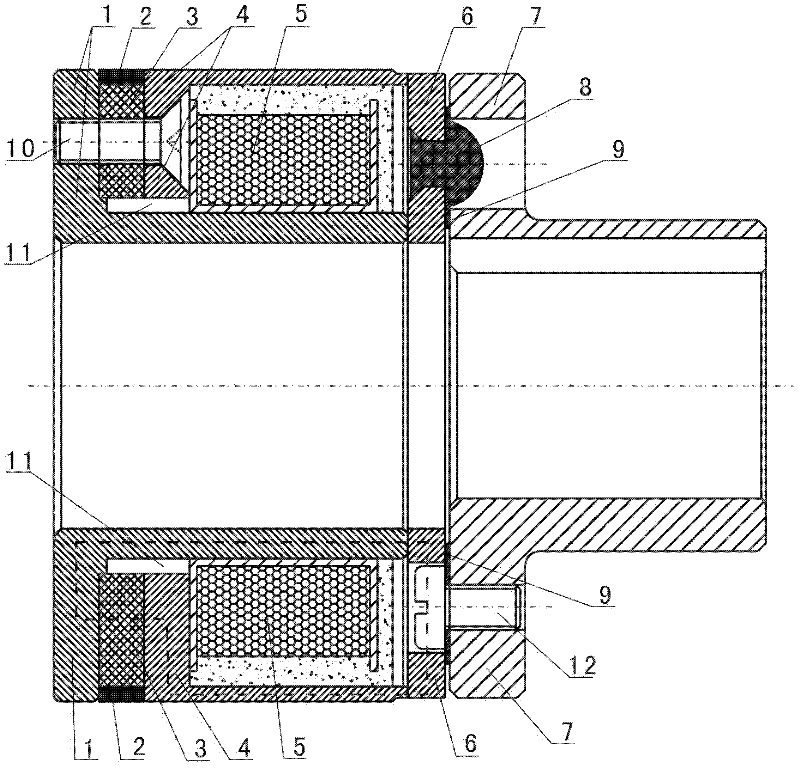
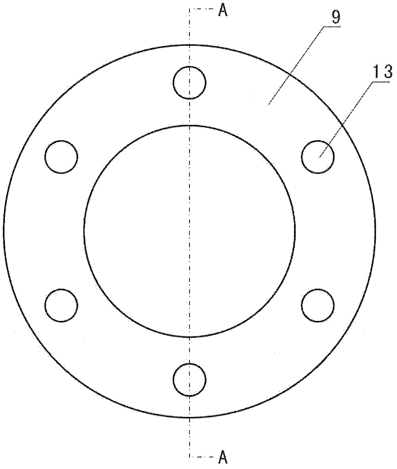
[0031] Such as figure 1 As shown, the present invention includes a stator assembly and a rotor assembly, and the structure of the stator assembly is: a coil assembly 5, an inner yoke 1, an outer yoke 4 and a permanent magnet 3, one end of the inner yoke 1 and the permanent magnet 3 One magnetic pole (N pole or S pole) is fixedly connected, the other magnetic pole (S pole or N pole) of the permanent magnet 3 is fixedly connected with one end of the outer yoke 4, and cross recessed countersunk screws 10 pass through the outer yoke respectively 4. The permanent magnet 3 and the inner yoke 1 are fixed, and the coil assembly 5 is installed in the gap between the inner yoke 1 and the outer yoke 4, and epoxy resin is potted around the coil assembly 5 to fix it; the rotor assembly The structure is: including the flange 7, the surface spring 9 and the armature 6, the flange 7...


PUM


Abstract

The invention discloses a permanent magnet powerless magnetic brake which comprises a stator assembly and a rotor assembly, wherein the stator assembly comprises a coil assembly, an inner yoke, an outer yoke and a permanent magnet, one end of the inner yoke is fixedly connected with one magnetic pole end of the permanent magnet, the other magnetic pole end of the permanent magnet is fixedly connected with one end of the outer yoke, and the coil assembly is arranged in a gap between the inner yoke and the outer yoke; the rotor assembly comprises a flange, a face-shaped spring and an armature, and the flange is connected with the armature through the face-shaped spring; and the other end of the inner yoke and the other end of the outer yoke are in tight surface-to-surface contact with the armature. The permanent magnet powerless magnetic brake provided by the invention has the advantages that the permanent magnet generates magnetic force to absorb the armature, thus realizing braking; and the structure is stable, the service life is long, the processing is simple, and the cost is low.

Description

technical field [0001] The invention relates to a brake, in particular to a permanent magnet electromagnetic brake, which belongs to the production field of electromagnetic brakes. Background technique [0002] Brakes are widely used in fields such as metallurgy, construction, chemical industry, food, machinery, transport ships, and article packaging, as braking devices for related mechanical rotating power equipment (mostly motors). [0003] The existing brakes are mainly structural brakes, which rely on the pressure generated by the deformation of the spring to act on the friction assembly, so that the friction assembly relies on the pressure provided by the spring to convert into friction force, thereby realizing braking. The application of this type of structural brake often has the following performance: (1) Spring: The spring is repeatedly compressed at high temperature for a long time, and it is prone to fatigue fracture, so that it cannot provide positive pressure to...

Claims


Application Information

Patent Timeline
IPC IPC(8): F16D65/27F16D65/22
Inventor 黄涛周小平肖平阳波黎启华廖世全杨凤军
Owner REACH MACHINERY ENTERPRISE
Why Eureka
Try Eureka