
Non-contact temperature measurement electromagnetic oven and temperature measuring method

A non-contact, electromagnetic cooker technology, applied in the direction of thermometers using directly heat-sensitive electric/magnetic elements, using electromagnetic means, thermometers, etc., can solve the problems of control principle description, and the prior art does not give any enlightenment, etc., To achieve the effect of increasing the degree of automation

Inactive Publication Date: 2011-11-09
叶小舟 +1
View PDF7 Cites 18 Cited by
  • Summary
  • Abstract
  • Description
  • Claims
  • Application Information

AI Technical Summary

Problems solved by technology

[0008] However, the case did not explain its control principle. Further research shows that the technical solution can only be realized under a series of specific conditions.
[0009] How to achieve a wider temperature range and continuous non-contact temperature control of the induction cooker, and explain it from the principle and mechanism, the existing technology does not give any inspiration

Method used


Image

  • Non-contact temperature measurement electromagnetic oven and temperature measuring method
  • Non-contact temperature measurement electromagnetic oven and temperature measuring method
  • Non-contact temperature measurement electromagnetic oven and temperature measuring method

Examples


Embodiment 1

[0076] In this embodiment, the temperature measurement process of an electromagnetic oven is used to illustrate the non-contact temperature measurement method of the present invention. See attached Figure 10 , 11 .

[0077] The induction cooker described in this embodiment includes: an induction cooker shell 2, an induction cooker platen 3, a heating coil 4 and a control circuit, wherein the control circuit includes a control board 1 and a driving board 8, and the center of the heating coil 4 is provided with a support frame 5 , the support frame 5 is equipped with a thermistor 7 .

[0078] A temperature-measuring induction coil 6 is also provided below the induction cooker platen 3, and the magnetic temperature-sensing element 10 is fixed together with the cooking heating pot 9, and the magnetic field change generated at a corresponding temperature point is converted into an electrical signal and output, and the temperature-measuring induction coil 6 is matched with the h...

Embodiment 2

[0086] In this embodiment, other is the same as Embodiment 1, the difference is that the magnetic temperature sensing element 10 is embedded in the position where the table top is in contact with the cooking heating pot 9, and the temperature-measuring induction coil and its substantially opposite place are placed under the table, An exciting coil is set independently, and the temperature is measured regularly when the heating coil is cut off. The temperature-measuring induction coil and the excitation coil are fixed below the induction cooker platen together by the support 5a, corresponding to the position of the magnetic temperature-sensing element, the support 5a is a plate frame whose longitudinal section is stepped, and the temperature-measuring induction coil and the excitation coil are the same The shaft is fixed on the board frame.

Embodiment 3

[0088] Others are the same as in Embodiment 1, the difference is that the temperature measuring induction coil 6 described in this embodiment adopts a Hall element. Specifically, this embodiment adopts a Hall element prepared by utilizing the Hall effect as the present embodiment. The temperature-measuring induction coil of the non-contact temperature-measuring method described in the invention is specifically: a rectangular sheet made of a uniform N-type semiconductor material, the sheet has a certain length, width, and thickness, and two sides in the length direction A voltage is applied to the terminal, and the position of the Hall element is within the effective range of the magnetic field of the magnetic temperature sensing element 10 .

[0089] When the magnetic temperature sensing element 10 causes the magnetic field B to change under the change of temperature, the change of the magnetic field B substantially perpendicular to the wide surface of the Hall element causes a...


PUM

PropertyMeasurementUnit
Curie pointaaaaaaaaaa

Abstract

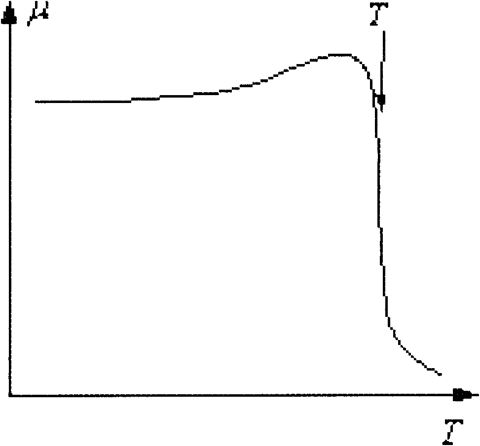
The invention discloses a non-contact temperature measurement electromagnetic oven and a temperature measuring method. The electromagnetic oven comprises an electromagnetic oven shell, an electromagnetic oven platen, a heating coil under the electromagnetic oven platen, a control circuit and a heating pot on the electromagnetic oven platen, as well as a magnetic temperature sensing element which is closely contacted with the bottom of the heating pot, a temperature measurement element which is arranged under the electromagnetic oven platen and corresponds to the magnetic temperature sensing element, wherein the temperature measurement element comprises a temperature measurement induction coil and a magnet exciting coil; the magnetic temperature sensing element is a ferromagnet or ferrimagnetics; a magnetic field of the magnetic temperature sensing element changes when the magnetic induction intensity of the magnetic temperature sensing element changes with temperature changes, by utilizing the temperature characteristics of the magnetic conductivity of the magnet and matching with the magnet exciting coil and the temperature measurement induction coil; and an electric signal of the corresponding temperature is generated when the change is reflected in the temperature measurement induction coil, and temperature detection and control are realized through the control circuit. According to the electromagnetic oven, the effect of automatic temperature control can be achieved, other set cooking functions can be realized, and the automatic degree of the electromagnetic oven is further improved.

Description

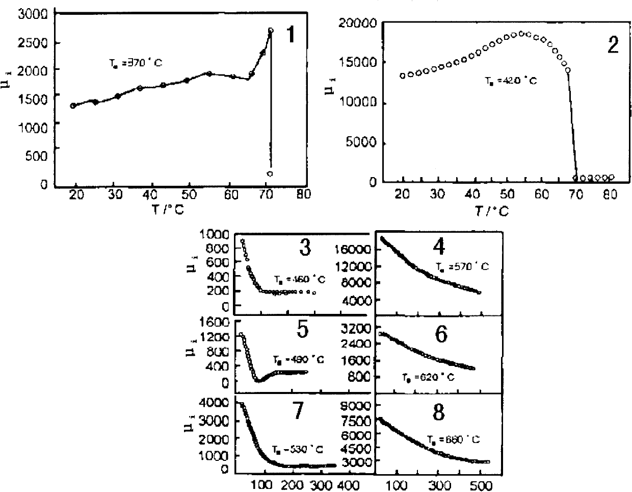
technical field [0001] The invention relates to an electromagnetic cooker and a temperature measuring method, in particular to an electromagnetic cooker and a temperature measuring method for realizing non-contact temperature measurement by utilizing the magnetic permeability temperature characteristics of iron or ferrimagnets. Background technique [0002] Usually, the oil temperature for frying food is about 160-170°C. If you want to deep-fry the food, the oil temperature is about 190°C. At 90-120°C, the bubbles disappear and the oil surface is calm; at 120-170°C, the oil temperature rises sharply, but the oil surface remains calm; at 170-210°C, there is a small amount of blue smoke and there are a few small ripples on the oil surface; once it reaches 210- At 250°C, a large amount of blue smoke containing acrolein will be formed, and various poisons such as thermal polymers of oil and polycyclic aromatic hydrocarbons will be produced. Therefore, temperature control in the ...

Claims


Application Information

Patent Timeline
Patent Type & Authority Applications(China)
IPC IPC(8): F24C7/08G01K7/38
Inventor 叶小舟彭霭钳刘劲旋林卫文武炜
Owner 叶小舟
Learn More