
Cone-shaped reverse diversion furnace gas circulation device

A circulation device and reverse technology, applied in the field of furnace gas circulation device structure, can solve problems such as uneven furnace temperature and atmosphere, reduced convective heat transfer capacity, and prolonged heating time, so as to improve hot air circulation efficiency, reduce resistance, and improve performance Improved effect

Active Publication Date: 2011-11-09
TLON TECHN FURNACES WUXI
View PDF7 Cites 9 Cited by
  • Summary
  • Abstract
  • Description
  • Claims
  • Application Information

AI Technical Summary

Problems solved by technology

[0002] In the prior art, the distance between the retort and the air guide tube of the horizontal heat treatment equipment is relatively large, and the speed of the airflow slows down when passing through the channel, resulting in reduced convective heat transfer capacity and prolonged heating time; the horizontal heating furnace adopts centrifugal fan blades , the airflow generated is rotating, and the stroke and time of the rotating airflow passing through the channel between the furnace tank and the air guide tube and the effective area of ​​the workpiece will be lengthened, resulting in a reduction in the number of air changes in the effective area of ​​the workpiece per unit time; horizontal heating furnace The workpiece material frame is usually a cuboid, and the air circulation system of the circular air guide tube will cause four large sectors to be formed between the workpiece and the circular air guide tube, so that the air flow avoids the workpiece and chooses the one with less resistance. The channel enters the air inlet of the fan blade, resulting in the reduction of the atmosphere entering the effective area of ​​the workpiece, resulting in uneven furnace temperature and atmosphere in the effective area, which seriously affects the quality requirements of heat-treated products

Method used


Image

  • Cone-shaped reverse diversion furnace gas circulation device
  • Cone-shaped reverse diversion furnace gas circulation device
  • Cone-shaped reverse diversion furnace gas circulation device

Examples


Embodiment Construction

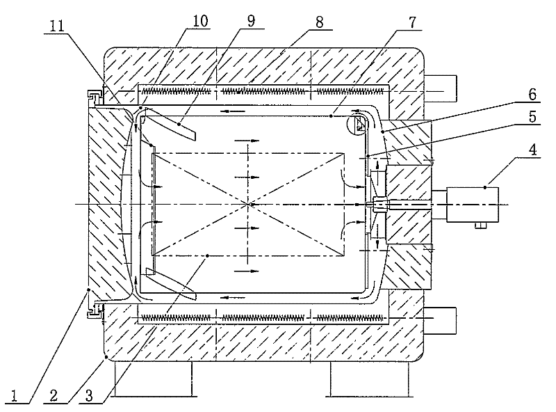
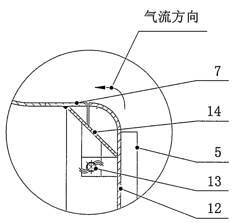
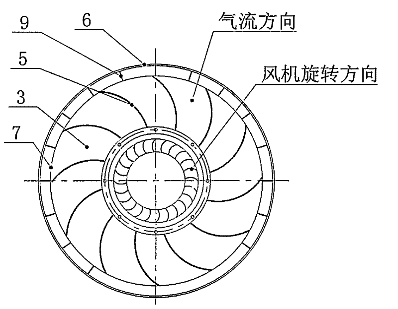
[0010] Such as Figure 1 ~ Figure 3 As shown, this embodiment includes: 1. furnace door, 2. shell, 3. workpiece, 4. circulating fan, 5. rear end reverse deflector, 6. furnace tank, 7. air guide tube, 8. heating Components, 9, front end reverse deflector 10, front conical deflector, 11, air flow baffle, 12, air guide plate, 13, bearing pin, 14, rear end conical deflector. The connection method is: the air guide tube (7) is installed in the furnace tank (6), one end of the rear conical guide plate (14) is welded on the inner side of the end of the guide tube (7), and the air guide plate (12) It is connected with the rear conical deflector (14) through the pin shaft (13), the rear reverse deflector (5) is welded on the wind deflector (12), and the rear reverse deflector (5) is installed The rear spiral direction is opposite to the rotation direction of the circulation fan (4), the circulation fan (4) is installed on the fan mounting seat of the furnace tank (6), and the front re...


PUM


Abstract

The invention discloses a technology of a furnace gas circulation device structure for a horizontal heat treating furnace, belonging to the field of heat treatment equipment. In the cone-shaped reverse diversion furnace gas circulation device, a novel furnace gas circulation structure combining cone-type diversion and reverse diversion is adopted, therefore, air flue resistance is reduced, hot wind circulation efficiency is improved, the distance in the airflow path is reduced by half, airflow passing speed is improved by more than one time, and the furnace temperature evenness degree of an effective working area in the furnace is improved to the temperature less than or equal to + / -3DEG C from + / -5DEG C so that the use ratio of the horizontal heat treatment furnace is obviously improved.Meanwhile, a cone-shaped diversion plate and front and back reverse diversion plates are artfully combined, and a welding or pin connecting mode is adopted on different positions to avoid air flue impact damage and thermal expansion influence at high temperature so as to effectively improve the safety and the reliability of using equipment.

Description

technical field [0001] The patent of the present invention belongs to heat treatment equipment, and specifically refers to the structural technology of a horizontal furnace gas circulation device with furnace tank heat treatment equipment. Background technique [0002] In the prior art, the distance between the retort and the air guide tube of the horizontal heat treatment equipment is relatively large, and the speed of the airflow slows down when passing through the channel, resulting in reduced convective heat transfer capacity and prolonged heating time; the horizontal heating furnace adopts centrifugal fan blades , the airflow generated is rotating, and the stroke and time of the rotating airflow passing through the channel between the furnace tank and the air guide tube and the effective area of ​​the workpiece will be lengthened, resulting in a reduction in the number of air changes in the effective area of ​​the workpiece per unit time; horizontal heating furnace The ...

Claims


Application Information

Patent Timeline
IPC IPC(8): F27D7/04
Inventor 刘一华湛宪宪田如好陈华方华吴靖
Owner TLON TECHN FURNACES WUXI
Learn More