Spiral optical fiber sensing device based on bending deformation of optical fiber

An optical fiber sensing, helical technology, applied in the direction of using optical devices, using optical devices to transmit sensing components, measuring devices, etc., can solve the uniformity of internal density and fine machining defects, limit sensor accuracy, and expand the scope of use and other problems, to achieve the effect of flexible use, convenient operation, and convenient processing and production.

Inactive Publication Date: 2011-11-09
XIAN JINHE OPTICAL TECH
View PDF0 Cites 15 Cited by
  • Summary
  • Abstract
  • Description
  • Claims
  • Application Information

AI Technical Summary

Problems solved by technology

But this sensor adopts elastic body 3, when the groove of helical deformer 1 is many and small, even when there is no force, the elastic body 3 sensitive to external temperature and air pressure will follow the groove of helical deformer 1. The change of the groove causes the signal fiber 10 to bend and cause interference and errors in the test results. The easy deformation of the high elastic body 3 of the rubber sheath will limit the increase in the number

Method used


Image

  • Spiral optical fiber sensing device based on bending deformation of optical fiber
  • Spiral optical fiber sensing device based on bending deformation of optical fiber
  • Spiral optical fiber sensing device based on bending deformation of optical fiber

Examples


Embodiment 1

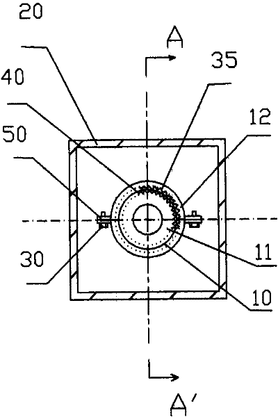
[0038] Such as image 3 , Figure 4As shown, the present invention includes an inner cylindrical body 11 and a housing 12 outside the inner cylindrical body 11 in an outer cavity 20, and a plurality of inner cylindrical outer surface grooves 40 are longitudinally distributed on the surface of the inner cylindrical body 11, On the inner surface of the housing 12 outside the inner cylindrical body 11, there are also a plurality of housing inner surface grooves 35 distributed along the longitudinal direction, and the outer surface grooves 40 of the inner cylindrical body are connected with the inner surface of the outer housing 12 of the inner cylindrical body 11. The grooves 35 on the inner surface of the housing are staggered, and there is a thread 60 on the surface of the inner cylindrical body 11. The signal optical fiber 10 is wound in the valley of the thread 60, and the signal optical fiber 10 is clamped by the groove 40 on the outer surface of the inner cylindrical body. ...

Embodiment 2

[0046] Such as Figure 5 As shown, in this embodiment, the difference from Embodiment 1 is that: one end of the signal fiber 10 is provided with a light reflection device, the other end of the signal fiber 10 is connected to the extension fiber 80, and the extension fiber 80 is connected to the 1X2 splitter 21 1 port, 2 ports of the 1X2 splitter 21 are respectively connected to the optical input and output ports of the test unit. In this embodiment, the structures, connections and working principles of other parts are the same as those in Embodiment 1.

Embodiment 3

[0048] Such as Figure 6 , Figure 7 As shown, in this embodiment, the difference from Embodiment 2 is that the inner cylindrical body 11 is a cuboid, and positioning grooves 70 are arranged side by side on the opposite two surfaces of the cuboid, and a part of the signal optical fiber 10 is fixed on the In the positioning groove 70, there are grooves 40 on the outer surface of the inner cylindrical body vertically distributed on the surface of the inner cylindrical body 11 with the positioning groove 70, and the outer surface grooves of the inner cylindrical body are arranged on the inner surface of the housing 12 correspondingly. The groove 35 on the inner surface, the signal optical fiber 10 is sandwiched between the grooves of the groove 40 on the outer surface of the inner cylinder and the grooves of the groove 35 on the inner surface of the housing.

[0049] When the inner cylindrical body 11 is crystal and the housing 12 is quartz glass, and the X-axis direction of the...


PUM


Abstract

The invention discloses a spiral optical fiber sensing device based on the bending deformation of an optical fiber. The optical fiber has a spiral multi-ring structure, so that the effective action length of the signal optical fiber is greatly prolonged; a plurality of opposite grooves are formed between an inner cylinder and a shell outside the inner cylinder, so that the dynamic range of the optical fiber sensing device is expanded under the condition that the bending curvature deformation of the signal optical fiber is greatly reduced; and different physical quantities are sensed by selecting different materials of the inner cylinder and the shell, so that the optical fiber sensing device can be applied to more occasions. The optical fiber sensing device has a simple structure, a reasonable design, high sensitivity, long service life, a good using effect and a wide application prospect, is convenient to process and manufacture and flexible in use, and can measure various physical quantities through extension.

Description

technical field [0001] The invention relates to an optical fiber sensing device in the field of sensing technology, in particular to an optical fiber sensing device including a spiral physical quantity test based on optical fiber bending deformation distributed between an inner cylindrical body and a casing. Background technique [0002] There are many types of fiber optic sensors, but the fiber optic microbend sensor is still a very promising fiber optic sensor with low cost and high precision. The microbend sensor has been proposed for 20 to 30 years, but Due to the unreasonable structural design, this type of sensor has not been used in large quantities, and there are even few mature commercial products on the market. [0003] In "Journal of Chengdu University of Science and Technology" 1990, No. 3, total No. 51, pages 65-70, "Study on the Structure and Performance of Optical Fiber Microbending Sensors", this article introduces a helical optical fiber microbending sensor....

Claims


Application Information

Patent Timeline
IPC IPC(8): G01D5/26G01D5/353G01K11/32G01B11/02G01K11/3206
Inventor 杜兵杜蔚杜迎涛
Owner XIAN JINHE OPTICAL TECH
Why Eureka
Try Eureka