A device for measuring land subsidence
A technology of ground subsidence and lever, applied in the direction of measuring device, using optical device, using optical device to transmit sensing components, etc., can solve the problems of difficult control and error in the actual situation, and achieve the effect of simple structure, high precision and accurate measurement
- Summary
- Abstract
- Description
- Claims
- Application Information
AI Technical Summary
Problems solved by technology
Method used
Image
Examples
Embodiment 1
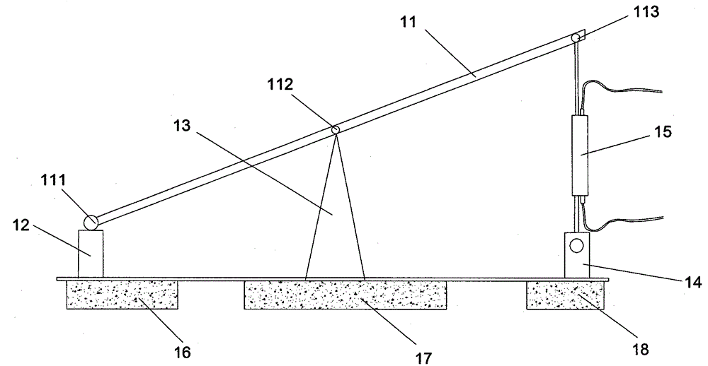
[0028] Such as figure 1 As shown, a device for measuring ground subsidence includes a lever 11, a first support 12, a second support 13, a third support 14 and a first fiber grating sensor 15, and the lever is made of a material with small variable The straight lever formed, its center of gravity is at the center of the lever, the fiber grating sensor includes a temperature detection device, the first support 12 is located directly below the left end of the lever 11, and the first support 12 The top is hinged with the left end 111 of the lever 11, the second support 13 is located in the middle of the first support 12 and the third support 14, and is located directly below the lever 11, the second support 13 The hinge point with the lever 11 is a fulcrum 112 , and the fulcrum 112 is on the line of the center of gravity of the lever 11 . The right end 113 of the lever 11 is hinged with one end of the first fiber grating sensor 15, and the other end of the first fiber grating se...
Embodiment 2
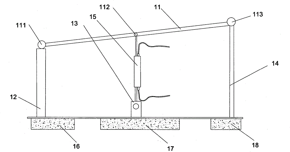
[0038] Such as figure 2 As shown, a device for measuring ground subsidence includes a lever 11, a first support 12, a second support 13, a third support 14 and a first fiber grating sensor 15, and the lever is made of a material with small variable The straight lever formed, its center of gravity is at the center of the lever, the fiber grating sensor includes a temperature detection device, the first support 12 is located directly below the left end of the lever 11, and the first support 12 The top is hinged with the left end 111 of the lever 11, the second support 13 is located in the middle of the first support 12 and the third support 14 and is located directly below the first fiber grating sensor 15, the first The fiber grating sensor 15 is located directly below the lever 11, one end of the first fiber grating sensor 15 is hinged to a point 112 in the middle of the lever 11, and the other end of the first fiber grating sensor 15 is connected to the first fiber grating s...
Embodiment 3
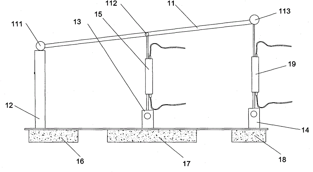
[0044] Such as image 3 As shown, a device for measuring ground subsidence includes a lever 11, a first support 12, a second support 13, a third support 14, a first fiber grating sensor 15 and a second fiber grating sensor 19, the lever A straight lever made of a material with a small shape change, its center of gravity is at the center of the lever, the fiber grating sensor includes a temperature detection device, the first support 12 is located directly below the left end 111 of the lever 11, And the top of the first support 12 is hinged with the left end 111 of the lever 11, the third support 14 is located directly below the right end 113 of the lever 11, and the top of the third support 14 is located at One end of the second fiber grating sensor 19 directly above the third support 14 is hinged, and the other end of the second fiber grating sensor 19 is hinged with the right end 113 of the lever 11. The second support 13 is located at the first support 12 In the middle of ...
PUM
 Abstract
Description
Claims
Application Information
 - R&D
- Intellectual Property
- Life Sciences
- Materials
- Tech Scout
- Unparalleled Data Quality
- Higher Quality Content
- 60% Fewer Hallucinations
Browse by: Latest US Patents, China's latest patents, Technical Efficacy Thesaurus, Application Domain, Technology Topic, Popular Technical Reports.
© 2025 PatSnap. All rights reserved.Legal|Privacy policy|Modern Slavery Act Transparency Statement|Sitemap|About US| Contact US: help@patsnap.com


