
Electromechanical device

A technology of electromechanical devices and electric power, applied in the direction of electromechanical devices, transmission devices, gear transmission devices, etc., can solve problems such as complex equipment, and achieve the effect of simple lubrication system

Active Publication Date: 2011-11-09
THE SWITCH DRIVE SYSTEMS OY +1
View PDF4 Cites 8 Cited by
  • Summary
  • Abstract
  • Description
  • Claims
  • Application Information

AI Technical Summary

Problems solved by technology

[0003] A challenging design aspect associated with the combination of a gearbox and an electric machine, which can be a generator and / or a motor, is the size and weight of the combination, among others
Furthermore, the equipment for lubricating, cooling and monitoring the combination of gearboxes and electrical machines can be complex compared to eg gearless systems

Method used


Image

  • Electromechanical device
  • Electromechanical device
  • Electromechanical device

Examples


Embodiment Construction

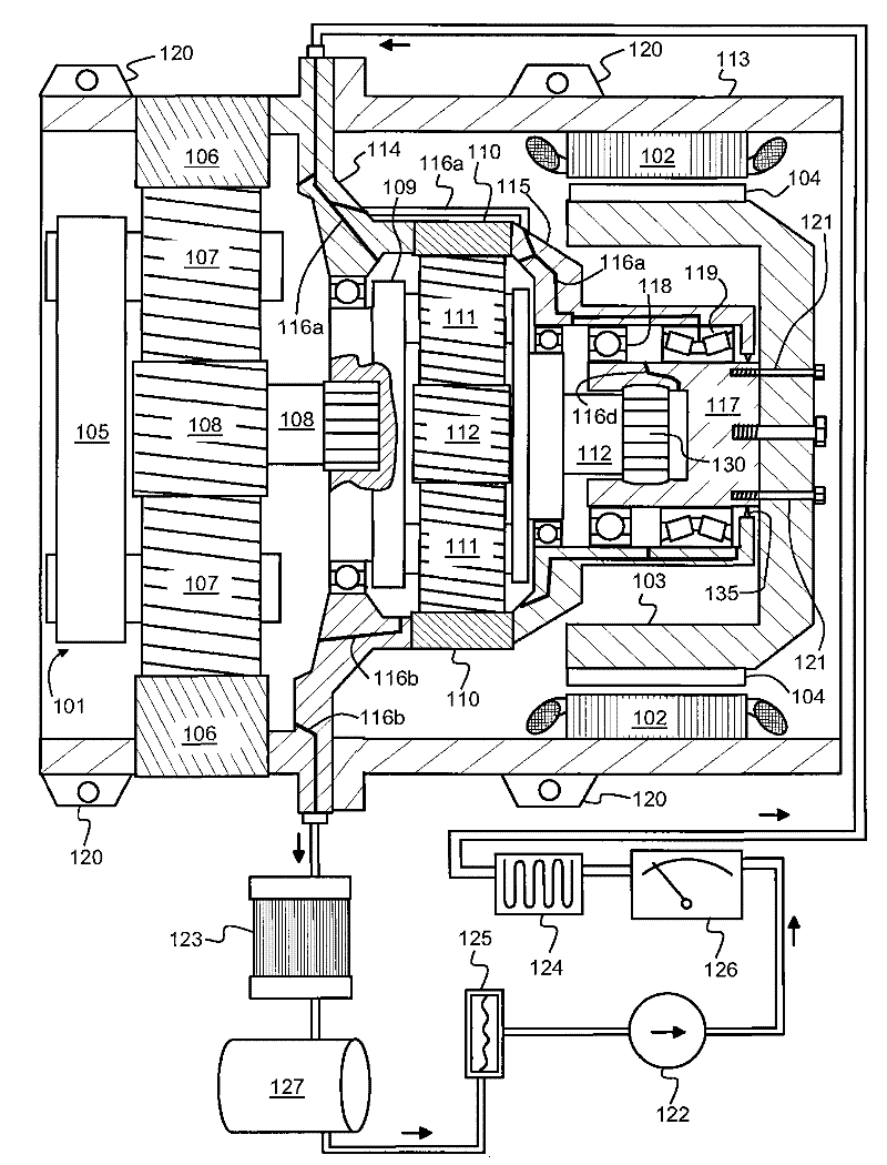
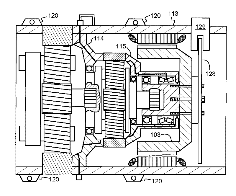
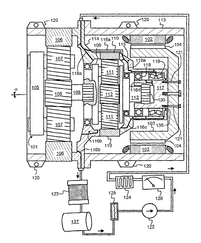
[0024] figure 1 A schematic cross-sectional view of an electromechanical device according to an advantageous exemplary embodiment of the invention is shown. The electromechanical device comprises a mechanical interface structure 101 for connection to an external rotating element, which can be, for example but not necessarily, a wind turbine. The electromechanical device includes an electric machine for converting mechanical power into electrical power or converting electrical power into mechanical power. The electric machine comprises a laminated stator core 102 provided with stator windings. The electric machine comprises a rotor comprising a central part 117, a frame 103 and permanent magnets 104 mounted on the outer surface of the frame. Of course, it is also possible that the central portion 117 and the frame 103 are a single integral piece. The electromechanical device includes one or more gear stages in the power transmission path between the mechanical interface stru...


PUM


Abstract

An electromechanical device comprises a mechanical interface structure (101) for connecting to an external rotating element, for example a wind turbine. The device comprises an electrical machine (102-104), and one or more gear stages (105-112) on a power transmission path between the mechanical interface structure and a rotor of the electrical machine. The device further comprises mechanical structures (113-115) constituting a common lubricant oil room for both the gear stages and the electrical machine. The electromechanical device comprises oil channels (116a) for directing lubricant oil circulated in the device to flow via the gear stages and via bearings (118, 119) of the electrical machine. Therefore, a common lubricating system can be used for both the gear stages and the electrical machine.

Description

technical field [0001] The invention relates to an electromechanical device which is a combination of one or more gear stages and a rotating electric machine. Background technique [0002] In many power generation systems, it may be advantageous from various design and construction points of view to connect the generator to a prime mover (such as a wind turbine) via a gearbox arranged to convert the rotational speed of the prime mover to Convert to speed range for generator. Accordingly, in many motor applications it may be advantageous to connect the electric motor to the actuator via a gearbox arranged to convert the rotational speed of the electric motor into a speed range suitable for the actuator. A gearbox may comprise one or more series of connected gear stages by means of which a desired gear ratio is achieved. Each individual gear stage can be, for example, a planetary gear stage or a spur gear stage. [0003] A challenging design aspect associated with the combi...

Claims


Application Information

Patent Timeline
IPC IPC(8): H02K7/116H02K5/16
CPCF03D11/0008F16H1/46Y02E10/72F03D11/02Y02E10/722F05B2260/98F03D80/70F03D15/00F03D15/10H02K7/10H02K9/197
Inventor 图奥马斯·沃莱-阿皮亚拉约尔马·蒂尔科宁维莱·帕卡里宁亚里·托伊卡宁奥林·柳科宁约尔马·穆斯塔拉赫蒂伊尔卡·马蒂凯宁
Owner THE SWITCH DRIVE SYSTEMS OY
Learn More