Beam-forming method of and device

A beamforming and parameter configuration technology, applied in the directions of space transmit diversity, diversity/multi-antenna systems, etc., can solve the problems that the system delay cannot be accurately pointed to the target UE, the signal demodulation error, and the calculation amount is too large. Speed, demodulation error reduction, and the effect of simplifying the calculation process

Active Publication Date: 2011-11-09
WUHAN HONGXIN TELECOMM TECH CO LTD
View PDF4 Cites 22 Cited by
  • Summary
  • Abstract
  • Description
  • Claims
  • Application Information

AI Technical Summary

Problems solved by technology

[0016] In view of this, the present invention provides a method and device for beamforming to overcome the system delay that cannot be accurately pointed

Method used


Image

  • Beam-forming method of and device
  • Beam-forming method of and device
  • Beam-forming method of and device

Examples


Embodiment 1

[0091] From the formulas (1), formula (2), formula (3) and formula (4) disclosed in the background art, it can be seen that in order to meet the requirements for beamforming accuracy and calculation speed, it is necessary to obtain the best SINR that can satisfy the maximum SINR The weight vector w is the weight coefficient.

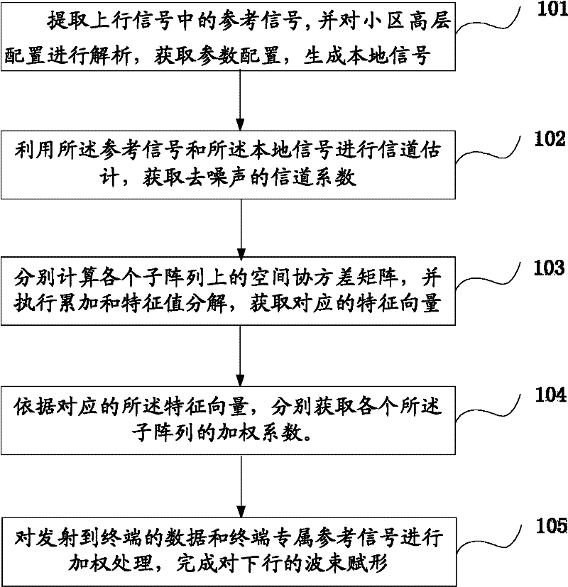
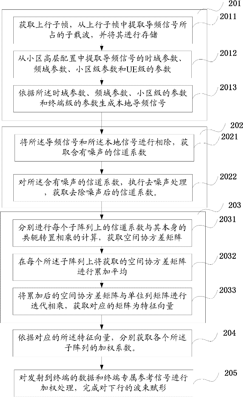
[0092] The beamforming method disclosed in Embodiment 1 of the present invention has the core idea of: generating a local signal by extracting corresponding parameters from the high-level configuration of the cell; and using the generated local signal in channel estimation processing to obtain The channel coefficient estimation results on each antenna; the spatial covariance matrix on the sub-array is calculated according to the estimated channel coefficients, and the data transmitted to the terminal and the terminal-specific reference signal are weighted to complete the beam assignment of the downlink shape.

[0093] Please refer to the attached figu...

Embodiment 2

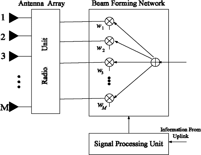
[0205] Such as Figure 6 As shown, it is a schematic structural diagram of a beamforming device disclosed in Embodiment 2 of the present invention, which mainly includes: a parameter analysis unit 101, a local signal generation unit 102, a channel estimation unit 103, a spatial covariance matrix calculation unit 104, and a subarray An eigenvalue decomposition unit 105 and a beamforming unit 106 .

[0206] The parameter parsing unit 101 is configured to extract a reference signal in the received uplink signal, and parse the high layer parameter configuration of the cell to obtain the parameter configuration of the reference signal.

[0207] The local signal generation unit 102 is configured to generate a local signal according to the parameter configuration of the reference signal.

[0208] The channel estimation unit 103 is configured to perform channel estimation by using the reference signal and the local signal, and obtain denoised channel coefficients.

[0209] The spati...


PUM


Abstract

The invention discloses a beam-forming method and device. The method comprises the following steps of: extracting a reference signal from uplink signals and resolving the high-level configuration of a cell to obtain the parameter configuration of the reference signal and generate a local signal; performing channel estimation by using the reference signal and the local signal to obtain a denoised channel coefficient; calculating a space covariance matrix on each subarray by using the channel coefficient; performing characteristic value decomposition on the covariance matrix to obtain a characteristic vector and further obtain a weighting coefficient accordingly; and weighting data transmitted to a terminal and an exclusive reference signal of the terminal by using the weighting coefficient to finish beam forming of a downlink. Due to the adoption of the steps in the method, the calculation process of beam forming is simplified, the beam forming realization speed can be effectively increased under the condition of ensuring a certain beam-forming accuracy, the time delay of a system is reduced, and the aims of pointing at a target terminal, reducing the signal demodulation errors and lowering the interference on other terminals are fulfilled.

Description

technical field [0001] The present invention relates to the technical field of wireless communication, and more specifically, to a beamforming method and device. Background technique [0002] In the wireless communication environment, the terminals are usually distributed in all directions of the base station. Due to the influence of the environment, the communication between the two will generate multipath signals, while the useful signals are distributed in a certain space. In order to ensure that the signals can be correctly demodulated , which puts high demands on signal reception and processing. In the existing LTE (Long Term Evolution, long-term evolution) system, the beamforming technology is usually used to combat interference, and at the same time, it can dynamically adjust the shape and direction of the beam according to the channel information, so that the UE (User Equipment, terminal ) to maximize the received signal, while using the clear directivity of the bea...

Claims


Application Information

Patent Timeline
IPC IPC(8): H04B7/06H04B7/08
Inventor 王强陈惠锋
Owner WUHAN HONGXIN TELECOMM TECH CO LTD
Why Eureka
Try Eureka