Flow-dividing flow-reducing device applied to facility fishery

A fishery and facility technology, applied in the fields of application, fish farming, animal husbandry, etc., can solve the problems of adverse effects on the stability of recreational fishery platforms, loss of net cage volume, and high cost of net cages, so as to increase fishermen's income and ensure stability , good flow reduction effect

Inactive Publication Date: 2011-11-16
ZHEJIANG OCEAN UNIV
View PDF2 Cites 9 Cited by
  • Summary
  • Abstract
  • Description
  • Claims
  • Application Information

AI Technical Summary

Problems solved by technology

However, due to the relatively high velocity of seawater in this area, the relatively large velocity of the ocean will have a relatively large impact on the culture volume of the cage, and will also have an adverse effect on the stability of the recreational fishery platform
Especially for the gravity-type anti-wind and wave cages currently used in China, under the action of large ocean currents, it is very easy to cause a large loss of cage volume, which greatly reduces the living space of the breeding objects, which leads to injuries and slow growth of the breeding objects. , easy to get disease, environmental pollution and other problems, which is not conducive to the sustainable development of cages
Moreover, it will cause drift and shake to the offshore fishing leisure and sightseeing platform popularized and applied in the southern coast of my country, which will have a negative impact on the development of the emerging recreational fishery.
Therefore, there is a need for a technical means to deal with the impact of ocean currents on the cage culture volume and to increase the stability of the offshore recreational fishery platform. At present, the coastal production units in southern my country have a group of cages empty at the front end of the front facing surface in front of the facility fishery facilities, which can play a role. However, due to the high cost of the net cage, a large amount of capital needs to be invested, resulting in economic waste

Method used


Image

  • Flow-dividing flow-reducing device applied to facility fishery
  • Flow-dividing flow-reducing device applied to facility fishery
  • Flow-dividing flow-reducing device applied to facility fishery

Examples


Embodiment Construction

[0015] The present invention will be further described in detail below in conjunction with the accompanying drawings and embodiments.

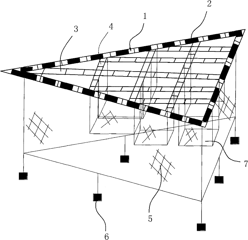
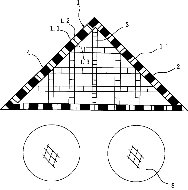
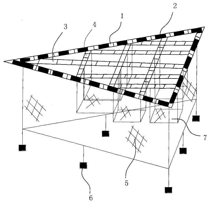
[0016] Such as figure 1 , figure 2 As shown, the present embodiment makes a right-angled isosceles triangular frame 1 with steel pipes. The triangular frame consists of two inner and outer frames 1.1, 1.3 and a connecting rod 1.2 welded between the two frames to form a passage for walking and operation. The triangular frame Five evenly distributed longitudinal passages 3 perpendicular to the bottom are set between the inner two waists and the bottom, and three uniformly distributed transverse passages 4 parallel to the bottom are arranged between the two waists. 4 is composed of two straight steel pipe support rods and the steel pipe connecting rod between them after welding, which is similar to the above, and can be used for walking, and the net cage float 2 is continuously bound on the triangular frame 1 and the longitudinal channel 3 in t...


PUM


Abstract

The invention discloses a flow-dividing flow-reducing device applied to a facility fishery, and the device provided by the invention is arranged between an incoming flow in an ocean flowing area and a fishery facility. The flow-dividing flow-reducing device is characterized by comprising a triangular frame, wherein floaters are arranged on the frame; a net is hung outside the frame; sinking stones are hung at the lower end of the net; one corner of the frame faces to the incoming direction of an ocean flow; a plurality of horizontal and lateral channels which are staggered and communicated are arranged in the triangular frame, thereby dividing the triangular frame into a plurality of frame grids; and a net bag used for cultivation is arranged under the grids. Compared with the flow-dividing flow-reducing effect of an idle net case, the flow-dividing flow-reducing effect of the triangular frame is better. The flow-dividing flow-reducing device has the advantages that the structure is simple, the manufacturing is convenient, materials are saved, and the cost is lower. Simultaneously, the grids can be used for hanging the net bag for culturing fishes, thereby improving the use ratio of the device and increasing the income of fisherman.

Description

technical field [0001] The invention relates to the technical field of fishery engineering, in particular to a flow diversion and flow reduction device for facility fishery. Background technique [0002] With the decline of marine aquatic resources, cage culture in facility fishery, as an important aspect of aquatic product farming, has developed rapidly, and facility fishery has also provided extensive platform support for offshore recreational fishery. In order to provide a better living environment for cultured animals and an improved working environment for recreational fisheries, cage culture areas and marine recreational fisheries should generally be set up in open sea areas with better water exchange. However, due to the relatively high velocity of seawater in this area, the relatively large velocity of the ocean current will have a relatively large impact on the culture volume of the cage, and will also have an adverse effect on the stability of the recreational fish...

Claims


Application Information

Patent Timeline
Patent Type & Authority Applications(China)
IPC IPC(8): A01K61/00
CPCY02A40/81
Inventor 宋伟华黄六一吴仁斌马家志
Owner ZHEJIANG OCEAN UNIV
Why Eureka
Try Eureka