Coal ash flotation separation equipment provided with reflection cone gas dispersing device

A separation equipment and gas device technology, applied in flotation, solid separation, etc., can solve problems such as unsatisfactory flotation effect, achieve good flotation effect, good flotation effect, and long contact time

Inactive Publication Date: 2013-08-14
FUJIAN LONGYAN LONGNENG FRYASH COMPREHENSIVE UTILIZATION
View PDF11 Cites 0 Cited by
  • Summary
  • Abstract
  • Description
  • Claims
  • Application Information

AI Technical Summary

Problems solved by technology

[0008] Most of the above technical solutions use a swirling device to make the bubbles move upwards in a swirling state, and the flotation effect is not ideal

Method used


Image

  • Coal ash flotation separation equipment provided with reflection cone gas dispersing device
  • Coal ash flotation separation equipment provided with reflection cone gas dispersing device
  • Coal ash flotation separation equipment provided with reflection cone gas dispersing device

Examples


Embodiment 1

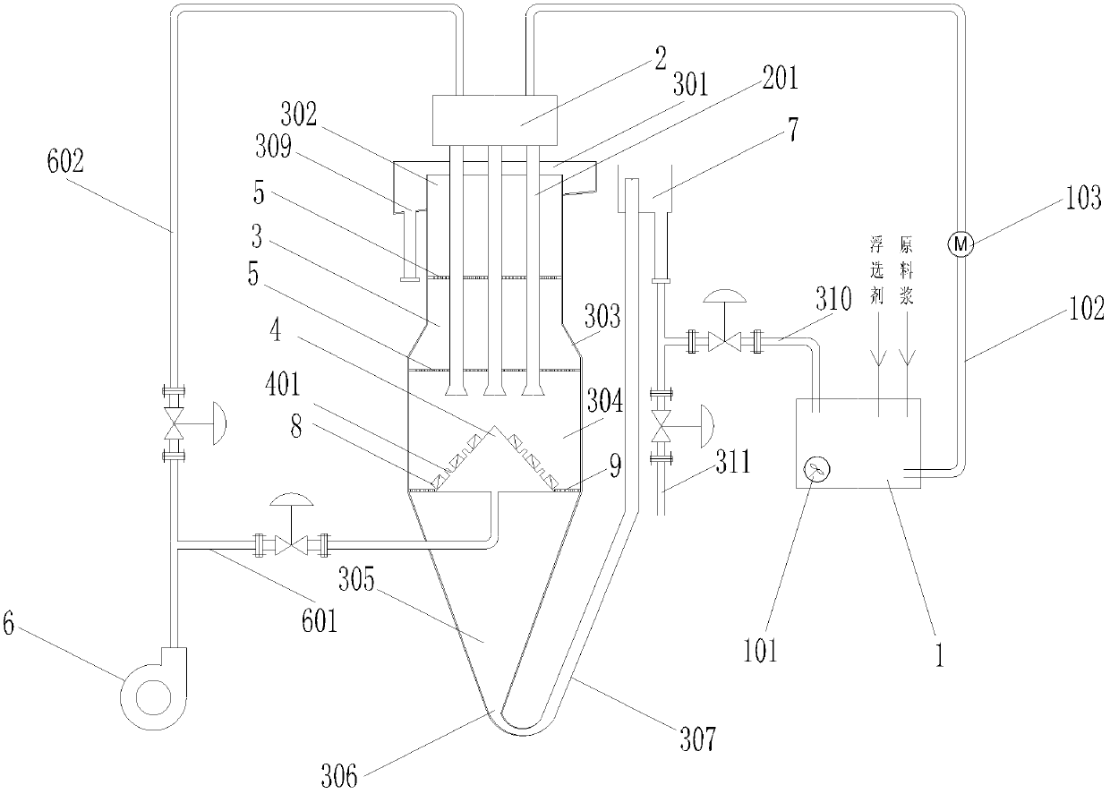
[0037] Such as figure 1 As shown, Embodiment 1 of the present invention includes: a material storage device 1, a distribution device 2, a vertical cylinder 3, a cone-shaped air diffuser 4, a multi-layer flotation plate 5, an air supply device 6, and a physical separation Devices such as ultrasonic separation device 8, tail ash box 7, filter plate 9, overflow collection section 301, tail ash collection section 305.

[0038] The cylinder body 3 arranged vertically can be divided into three parts, from top to bottom: the first flotation section 302 , the diffusion cone section 303 , and the second flotation section 304 . Wherein, the first flotation section 302 is relatively thin, and a layer of flotation plates 5 is arranged inside it. The second flotation section 304 is relatively thick, and a cone-shaped air diffuser 4 and a layer of flotation plates 5 are arranged in it. The diffusion cone section 303 is located between the first flotation section 302 and the second flotati...

Embodiment 2

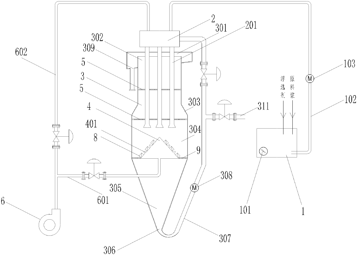
[0048] figure 2 Shown is embodiment 2 of the present invention, and its difference with embodiment 1 is: 1, the number of distributing pipeline 201 is 6; 3. The tail ash pipeline 307 is provided with a slurry pump 308; 4. The tail ash pipeline 307 is also provided with a branch pipeline as the ash discharge pipeline 311, the tail ash pipeline 307 and the discharge pipeline Ash pipes 311 are provided with valves. Similarly, according to the composition and process requirements of the fly ash, the tail ash can re-enter the flotation separation equipment through the tail ash pipeline 307 for flotation to recover the carbon particles therein; when the carbon content in the tail ash is too low, the Ash discharge pipe 311 discharges.

Embodiment 3

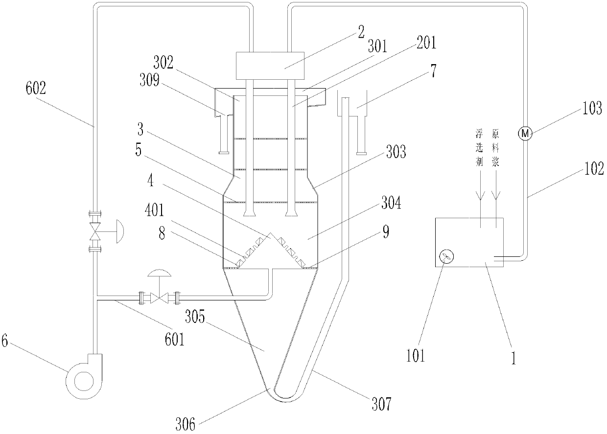
[0050] image 3 Shown is embodiment 3 of the present invention, and its difference with embodiment 1 is: 1, flotation plate is 3 layers; 2, the number of distribution pipeline 201 is 4; 3, tail ash box 7 is positioned at tail ash pipeline 307 and set outside the tail ash pipe 307, the height of the end of the tail ash pipe is above the top flotation plate, and the end of the tail ash pipe is provided with a liquid level regulating device for adjusting the height of the end of the tail ash pipe ; 4. There is no circulation pipeline 310 between the tail ash box 7 and the storage device 1 .


PUM


Abstract

The invention discloses a fly ash flotation separation device with a reflective cone bucket air diffuser, which comprises a vertical cylinder, an overflow collection section at the top and a tail ash collection section at the bottom; The gas diffuser in the body; the multi-layer flotation plates arranged at intervals in the cylinder; the distribution device located on the upper part of the overflow collection section; the gas supply device, which communicates with a plurality of air holes on the gas diffuser through the first gas pipeline. The advantages of the present invention are: 1. The bubbles combined with carbon particles are reflected to more angles by the cone-shaped air diffuser, and the reflection effect is better than that of plane reflection; 2. The air spray of the air diffuser drives the bubbles to a turbulent state Float in all directions in the cylinder to achieve better flotation effect; 3. Bubbles that do not pass through the flotation plate are reflected by the cone-shaped air diffuser, which intensifies the effect of turbulent flow and improves the flotation rate.

Description

technical field [0001] The invention relates to a fly ash flotation separation device used in the production of activated carbon from fly ash, more specifically, the invention relates to a fly ash flotation separation device with a reflective cone bucket air diffuser. Background technique [0002] Fly ash is one of the largest industrial wastes in my country, and the annual slag discharge in China has reached 30 million tons at this stage. With the development of the power industry, the discharge of fly ash from coal-fired power plants is increasing year by year. Fly ash contains a large amount of unburned carbon particles, which can be used as a raw material for the manufacture of activated carbon after flotation. [0003] Chinese patent 200810031474.7 discloses a special flotation column for fly ash. A slurry distributor is installed on the top of the flotation column cylinder. Multi-layer bubbling plates are arranged inside the cylinder. The ash overflow hole, the pulp ...

Claims


Application Information

Patent Timeline
Patent Type & Authority Patents(China)
IPC IPC(8): B03D1/14
Inventor 许闽清
Owner FUJIAN LONGYAN LONGNENG FRYASH COMPREHENSIVE UTILIZATION
Why Eureka
Try Eureka