Steam drive exploitation method for heavy oil reservoir

A production method and technology for heavy oil reservoirs, which are applied in the fields of production of fluids, earth-moving drilling, wellbore/well components, etc., can solve the problems of low utilization rate of steam heat energy, steam channeling, and no description of potential safety hazards, and achieve high thermal efficiency. Effectiveness of utilization efficiency and recovery factor, increasing fluidity and oil quality, and improving oil displacement seepage conditions

Inactive Publication Date: 2011-11-16
PETROCHINA CO LTD
View PDF9 Cites 21 Cited by
  • Summary
  • Abstract
  • Description
  • Claims
  • Application Information

AI Technical Summary

Problems solved by technology

[0007] One is the problem of deep burial and large heat loss along the steam
For medium-deep reservoirs (500-1400m), under the previous technological conditions, the dryness of the bottom hole is difficult to meet the requirements
[0008] Theoretical calculation and actual measurement of wellbore heat loss show that: under the condition of light oil pipe steam injection, hot water will be turned into hot water below 800m depth; under the condition of steam huff and puff heat insulation technology, the dryness of steam below 800m depth will be reduced to 30-35%. Thermal technology cannot meet the demand for steam dryness in mid-deep steam flooding
[0009] The second is the problem of high steam injection pressure and low utilization rate of steam heat energy under the condition of middle and deep layers
Therefore, this document does not explain how to control the injected air in the process of steam flooding to avoid the safety hazard of detonating the mixed gas of oil, gas and oxygen
[0014] In the existing technology, there are still problems of large steam heat loss and low heat utilization rate inside the oil layer
In order to ensure the effect of steam flooding development, it is necessary to increase the intensity of steam injection and increase the amount of steam injection during the on-site implementation process. On the one hand, this will cause a great waste of energy; The phenomenon of steam channeling between production wells is serious, resulting in low steam swept volume and a sharp drop in steam flooding oil production rate

Method used


Image

  • Steam drive exploitation method for heavy oil reservoir
  • Steam drive exploitation method for heavy oil reservoir
  • Steam drive exploitation method for heavy oil reservoir

Examples


Embodiment

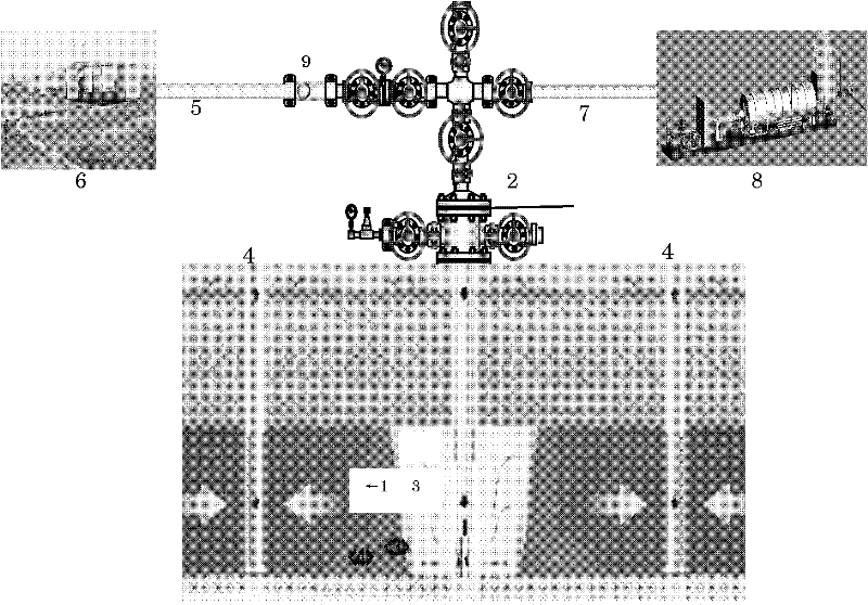
[0057] Such as figure 1 As shown, in the heavy oil layer 1, the steam flooding injection-production well pattern is deployed between the steam injection well 2 and the production well 4 in a reverse nine-point manner, and both the steam injection well and the production well are completed in a prestressed manner.

[0058] A long-term heat-insulated steam injection pipe string 3 is lowered into the steam injection well to reduce steam heat loss and improve the dryness at the bottom of the well. The long-term heat insulation steam injection pipe string 3 used is composed of E-grade heat insulation pipe, QK331-152 high temperature long-term steam drive packer, Y441-152 forced unsealing steam drive packer, JM-100 heat insulation pipe connection A long-term heat-insulated steam injection string composed of hoop sealer and heat-insulated telescopic pipe.

[0059] Among them, the E-class heat-insulated pipe is a vacuum heat-insulated pipe, which adopts a prestressed vacuum heat-insu...


PUM


Abstract

The invention belongs to the field of oil exploitation, and relates to a steam drive exploitation method for a heavy oil reservoir, in particular to a steam drive exploitation method of intermediate-deep layer heavy oil aided by injecting air. The method comprises the following steps of synchronously and continuously injecting steam and air in a steam injection well according to a certain mass ratio in the process of intermediate-deep layer heavy oil steam drive production, and performing a low-temperature oxidation reaction between crude oil and oxygen. According to the method disclosed by the invention, heat utilization and recovery ratio of intermediate-deep layer heavy oil steam drive can be improved; a problem of steam channeling among injection and exploitation wells can be eased, and development effect of steam drive can be improved.

Description

technical field [0001] The invention belongs to the field of oil exploitation, and relates to a steam flooding mining method for heavy oil reservoirs, in particular to a mid-deep heavy oil air injection assisted steam flooding mining method. Background technique [0002] Heavy oil is an important petroleum resource in the 21st century. The reserves of heavy oil, super heavy oil and natural bitumen in the world are about 1000×10 8 tons, accounting for 53% of the world's remaining recoverable oil reserves, mainly distributed in Canada, Venezuela, the United States, China and other countries and regions. Heavy oil accounts for 40% of my country's remaining recoverable oil reserves, of which medium-deep heavy oil accounts for 70%. [0003] The way of heavy oil production is mainly to take measures to improve the fluidity of crude oil, increase the oil-water mobility ratio and increase the displacement efficiency of crude oil. At present, heavy oil recovery is mainly based on t...

Claims


Application Information

Patent Timeline
Patent Type & Authority Applications(China)
IPC IPC(8): E21B43/24
Inventor 蒋生健杨公鹏郎成山王少武曲金明康党辉
Owner PETROCHINA CO LTD
Why Eureka
Try Eureka