Hot air dryer

A dryer and hot air technology, applied in progressive dryers, dryers, heating to dry solid materials, etc., can solve the problems of high work intensity, frequent switching, unstable temperature, etc., to achieve convenient equipment maintenance and avoid bumps The effect of damage and avoidance of workpiece damage

Inactive Publication Date: 2011-11-16
天津杰科同创科技发展有限公司
View PDF6 Cites 7 Cited by
  • Summary
  • Abstract
  • Description
  • Claims
  • Application Information

AI Technical Summary

Problems solved by technology

The drying equipment currently used is a drawer-type layered structure. Workers put the workpiece flat in the drawers of each layer, close the door to seal the oven, and the fan blows hot air from the bottom of the oven to dry the workpiece. The existing equipment mainly has the following Problems: 1. The workpieces are placed in layers, and the temperature of the drawers on each layer is inconsistent and difficult to control, resulting in inconsistent quality of the workpieces; 2. The space in the original oven is small, and it is easy to cause collisions and damage to the workpieces when picking and placing the workpieces; 3. Picking and placing the workpieces It is necessary to open and close the box door frequently, which consumes a lot of energy, and the work intensity is high and the work efficiency is low; 4. The drawer slides of the original equipment are easily damaged and difficult to replace, which is not easy to maintain; 5. The original equipment does not have a hot air recovery device, and the tail after drying Wind requires factory fitted plumbing
[0003] In short, the original process uses a drawer-type oven or a door-type oven. The drying temperature of the workpiece is unstable and the drying time is artificially controlled, resulting in overdrying (drying time is too long), or drying is too soft (drying time is not enough), resulting in The surface of the door panel is poorly bonded and the strength is poor. There is no good solution to this problem in the industry

Method used


Image

  • Hot air dryer
  • Hot air dryer
  • Hot air dryer

Examples


Embodiment Construction

[0018] The present invention will be further described in detail below in conjunction with the accompanying drawings and through specific embodiments. The following embodiments are only descriptive, not restrictive, and cannot limit the protection scope of the present invention.

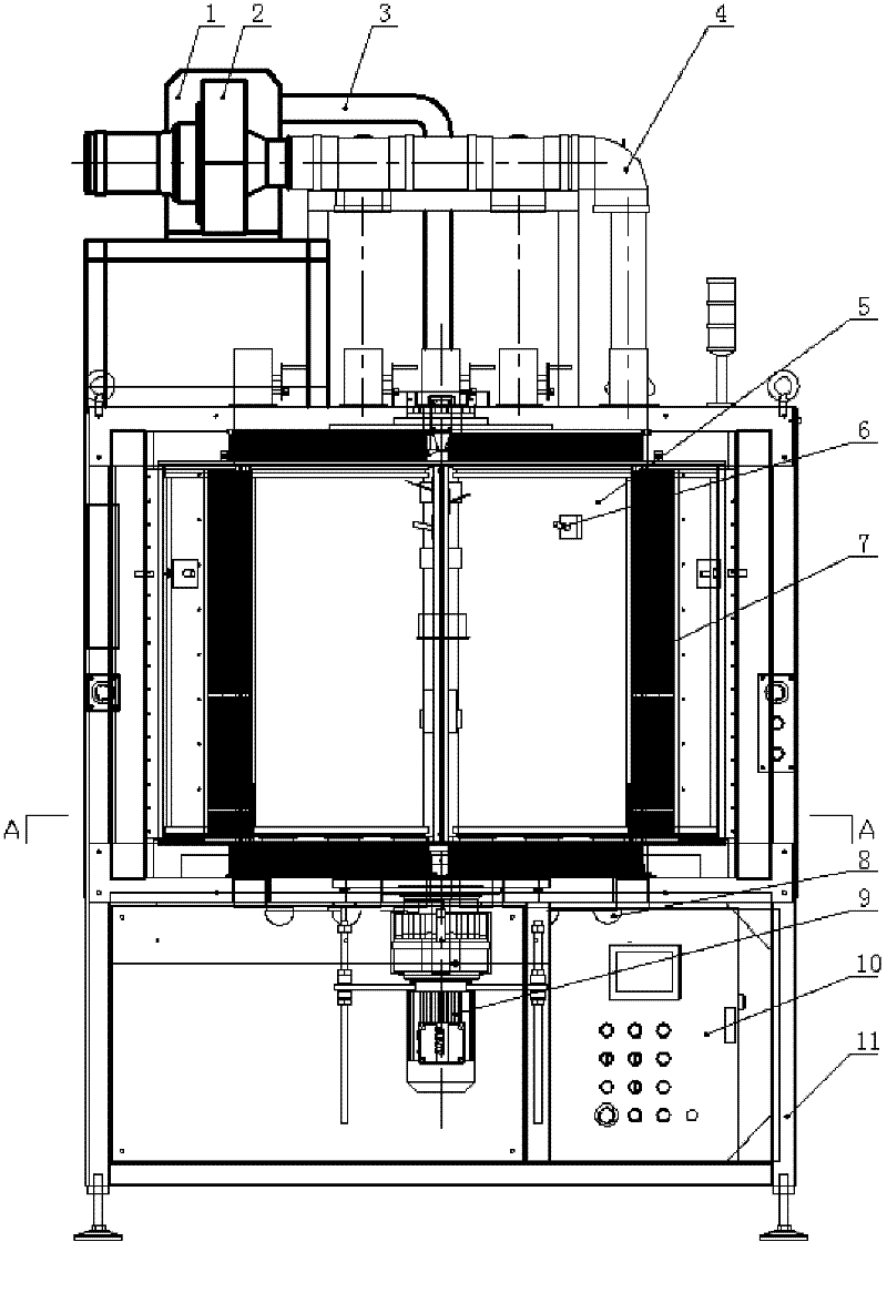
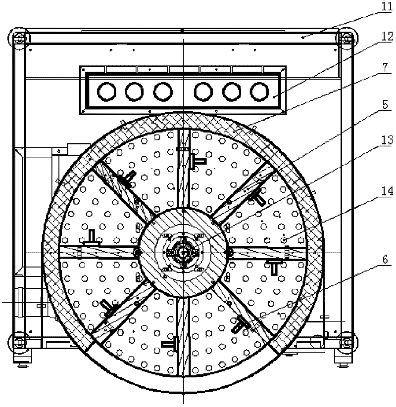
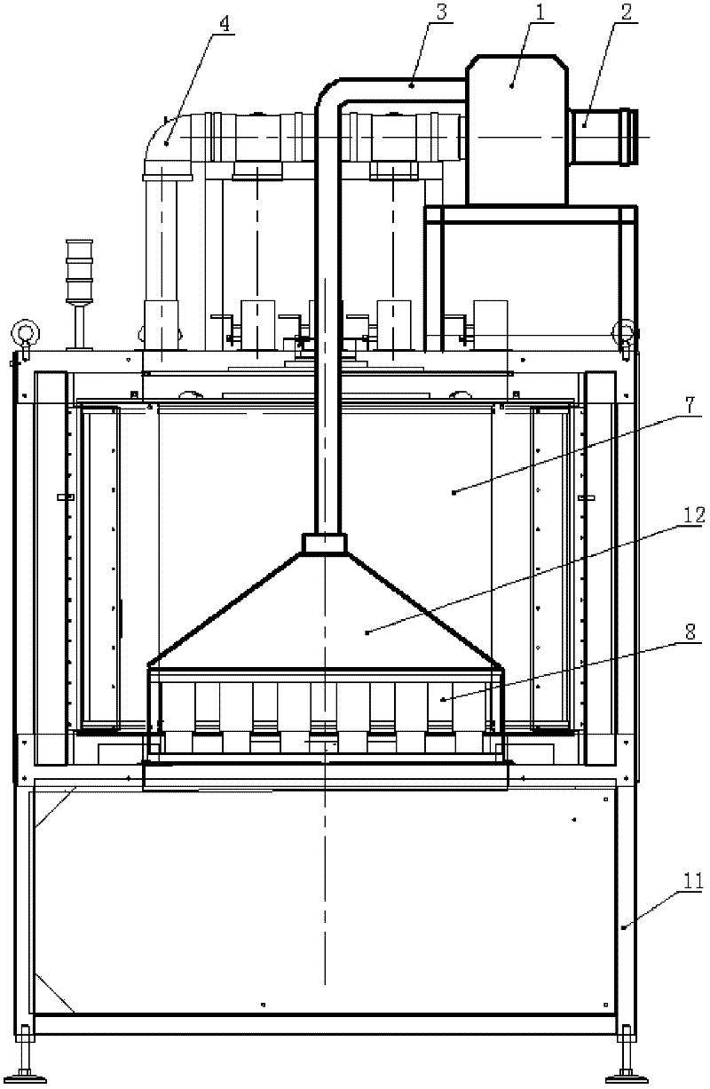
[0019] A hot air dryer, comprising a frame 11, an oven shell 7, a heating device 1, a fan 2 and a temperature controller 10, the oven shell is fixed on the frame, and the heating device and the fan are fixed on the top plate of the oven shell, The heating equipment sends hot air into the oven shell through the main air inlet pipe 3, and the fan is connected to the return air pipe 4 installed on the top plate of the oven shell, and the heating equipment and the temperature of the oven are controlled by a temperature controller.

[0020] The innovation point of the present invention is:

[0021] The oven shell is vertically cylindrical, and a rotating shaft 13 is coaxially installed on the bottom plate...


PUM


Abstract

The invention relates to a hot air dryer, which comprises a rack, a drying oven shell, heating equipment, an air blower and a temperature controller. The drying oven shell is in a vertical cylinder shape; a rotation shaft is coaxially installed on a bottom plate in the drying oven shell; the lower end of the rotation shaft extends out of the bottom plate of the drying oven and is provided with a stepping driving motor; pedant baffle plates are uniformly and fixedly installed on the rotation shaft on the bottom plate in the drying oven shell in a radial direction; the inner space of the drying oven shell is divided into eight equational drying areas by the pedant baffle plates; a pendant hook is fixedly installed on each pedant baffle plate; uniform air holes are formed in the bottom plate; the front end of the drying oven shell corresponds to two drying areas to form open drying areas; the other six drying areas are closed drying areas; and outer-side edges and top edges of the pedant baffle plates are hermetically matched with the drying oven shell in a sliding manner. The hot air dryer adopts a rotary mode to work, workpieces are hung on the pedant baffle plates and uniformly dried by hot air, the temperature in a closed drying area is constant, so the stable quality of the workpieces are effectively ensured, and the workpieces are prevented from being knocked and damaged. Moreover, the device is convenient to operate and easy to maintain, and has high working efficiency and long service.

Description

technical field [0001] The invention belongs to the field of automobile assembly field, in particular to a hot air dryer. Background technique [0002] After the inner frame of the car door panel is made from the injection molding machine, it needs to be installed with skin bonding. The fixing of the colloid needs to be kept at a certain temperature for a period of time to achieve the best bonding effect. The drying equipment currently used is a drawer-type layered structure. Workers put the workpiece flat in the drawers of each layer, close the door to seal the oven, and the fan blows hot air from the bottom of the oven to dry the workpiece. The existing equipment mainly has the following Problems: 1. The workpieces are placed in layers, and the temperature of the drawers on each layer is inconsistent and difficult to control, resulting in inconsistent quality of the workpieces; 2. The space in the original oven is small, and it is easy to cause collisions and damage to the...

Claims


Application Information

Patent Timeline
Patent Type & Authority Applications(China)
IPC IPC(8): F26B15/04F26B3/06F26B21/02F26B25/22
Inventor 孙霁鹏苑长伟闫绍恒秦红升
Owner 天津杰科同创科技发展有限公司
Why Eureka
Try Eureka