Unlock instant, AI-driven research and patent intelligence for your innovation.

Detection system for tamping settlement of heavy tamping machine

A detection system and tamping technology, which is applied in the field of foundation soil survey, construction, infrastructure engineering, etc., can solve the problems of high labor intensity, large impact on the vehicle body, troublesome detection, etc., achieve high detection accuracy and avoid waste , high reliability effect

Inactive Publication Date: 2011-11-23
DALIAN UNIV OF TECH +1
View PDF6 Cites 28 Cited by
  • Summary
  • Abstract
  • Description
  • Claims
  • Application Information

AI Technical Summary

Problems solved by technology

[0006] 1. The inspectors enter the ram pit for inspection. This inspection method is time-consuming and laborious, and the inspection is not accurate and there are certain risk factors for the inspectors.
[0007] 2. The testing personnel move the testing equipment to the side of the rammed pit, and use laser range finder, sonic range finder and other equipment for detection. Although this detection method has high precision, the equipment is more expensive and the equipment must be moved for each detection. To the side of the ramming pit, and then removed after the test, the test is troublesome and labor-intensive
[0010] However, this online detection system is too complicated. The main arm detection mechanism needs a pressure sensor, signal amplification and shaping circuit, and the depth test unit needs a laser depth sensor and signal conditioning circuit. The cost is high, and the laser depth sensor is installed at the front end of the main arm, which is troublesome to install , the falling of the rammer has a greater impact on the car body, and the impact of uncertain factors such as main arm shaking and wind force greatly shortens the service life of the laser depth sensor and increases the error in detecting the amount of tamping.

Method used


Image

  • Detection system for tamping settlement of heavy tamping machine
  • Detection system for tamping settlement of heavy tamping machine
  • Detection system for tamping settlement of heavy tamping machine

Examples


Embodiment Construction

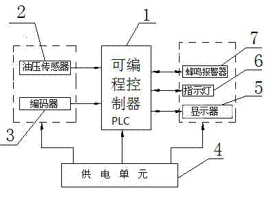
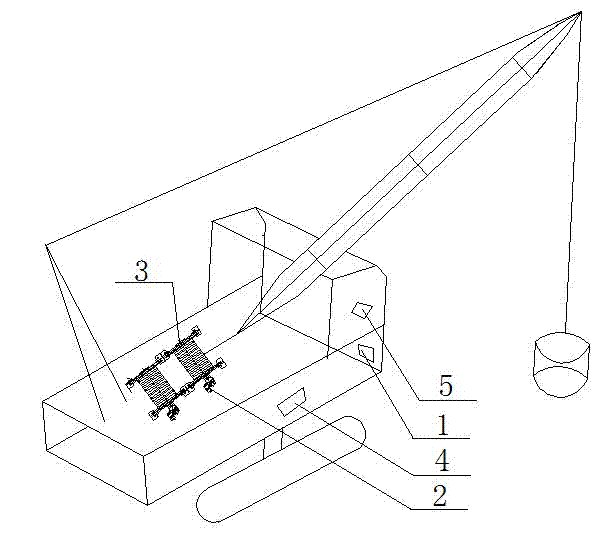
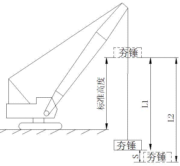
[0035] as attached Figure 1-4 Said, a dynamic tamping machine tamping weight detection system, based on the dynamic tamping machine; this system includes: programming controller PLC1, oil pressure sensor 2, encoder 3 and display 5; said programming controller PLC1 input terminal It is connected with the oil pressure sensor 2 and the encoder 3, and the output end is connected with the display 5; the input end of the oil pressure sensor 2 is connected with the winch motor, and the output end is connected with the programming controller PLC1; the oil pressure sensor 2 will detect The pressure value is transmitted to the programming controller PLC1; the input end of the encoder 3 is connected to the winch motor, and the output end is connected to the programming controller PLC1; the encoder 3 transmits the length of the detection wire rope to the programming controller PLC1 The input terminal of the display 5 is connected with the programming controller PLC1, and the dynamic comp...


PUM


Abstract

The invention discloses a detection system for the tamping settlement of a heavy tamping machine, wherein the heavy tamping machine is taken as a foundation. The detection system comprises a programmable logic controller (PLC), an oil pressure sensor, a coder and a displayer, wherein the input end of the PLC is connected with the oil pressure sensor and the coder; the output end of the PLC is connected with the displayer; the input end of the oil pressure sensor is connected with a winch motor; the output end of the oil pressure sensor is connected with the PLC; the oil pressure sensor is used for transmitting a detected pressure value to the PLC; the input end of the coder is connected with the winch motor; the output end of the coder is connected with the PLC; the coder is used for transmitting the detected rope folding length of a steel wire rope to the PLC; the input end of the displayer is connected with the PLC; and the tamping settlement of the heavy tamping machine in one-time operation is displayed through the display. By adopting the PLC, the detection system disclosed by the invention has high detection precision and small error and can be used for various heavy tamping devices; in addition, the detection system has the advantages of convenience for mounting, simpleness for debugging, high reliability and low prices.

Description

technical field [0001] The invention relates to the technical field of engineering machinery, in particular to a detection system for the tamping sinkage of a dynamic tamping machine, which is used for automatically detecting the tamping sinkage of the dynamic tamping machine. Background technique [0002] Dynamic tamping machine is one of the indispensable large-scale equipment in modern construction sites, and it has been widely used in mountain reclamation, sea reclamation, and mountain backfill foundation treatment. The working process of the dynamic tamping machine is to repeatedly lift the 80-400KN hammer (the heaviest up to 2000KN) to a height of 8-25m (the highest up to 40m), and then use the automatic decoupling to release the load or drop the hammer freely to form a powerful hammer on the way. Shock waves and high stress, thereby increasing the strength of the foundation, reducing compressibility, improving the ability to resist vibration and liquefaction, and eli...

Claims


Application Information

Patent Timeline
IPC IPC(8): E02D1/00
Inventor 高顺德王欣曾洪勇张洪民
Owner DALIAN UNIV OF TECH
Features
  • R&D
  • Intellectual Property
  • Life Sciences
  • Materials
  • Tech Scout
  • Unparalleled Data Quality
  • Higher Quality Content
  • 60% Fewer Hallucinations
Learn More