Steel-mesh separation wall

A technology of steel mesh and mesh, applied in the direction of walls, building components, buildings, etc., can solve the problems of easy falling off of horizontal bars and longitudinal bars, irregular construction and installation quality, deformation, etc.

Inactive Publication Date: 2011-11-23
刘德政
View PDF6 Cites 15 Cited by
  • Summary
  • Abstract
  • Description
  • Claims
  • Application Information

AI Technical Summary

Problems solved by technology

However, during the transportation and installation process of this technical solution, the transverse and longitudinal r

Method used


Image

  • Steel-mesh separation wall
  • Steel-mesh separation wall
  • Steel-mesh separation wall

Examples


Embodiment 1

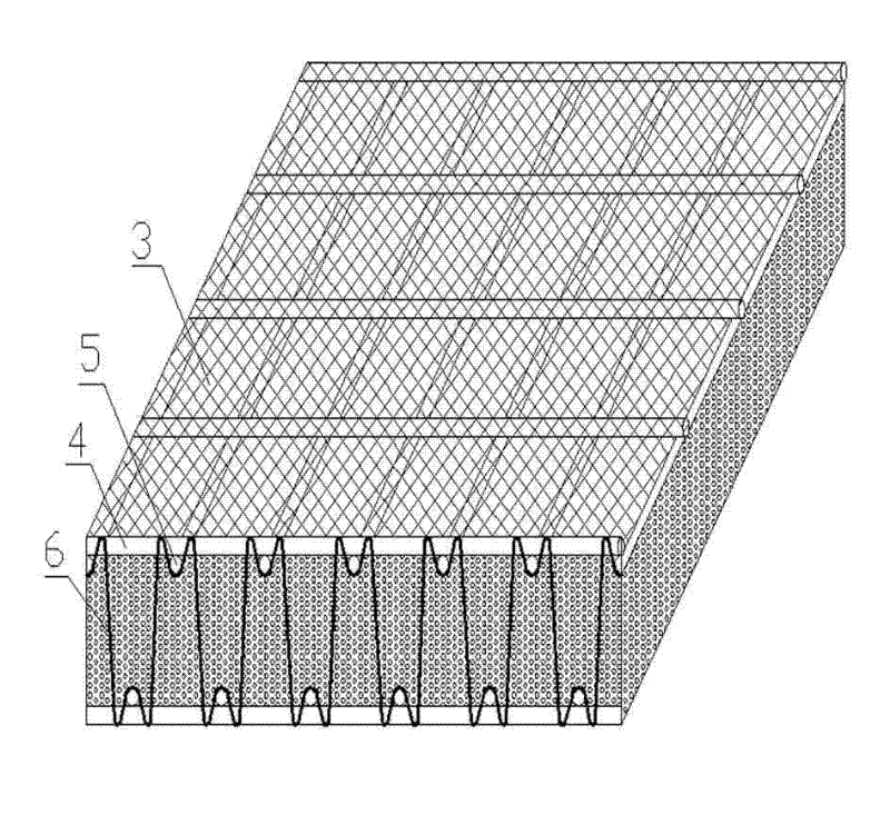
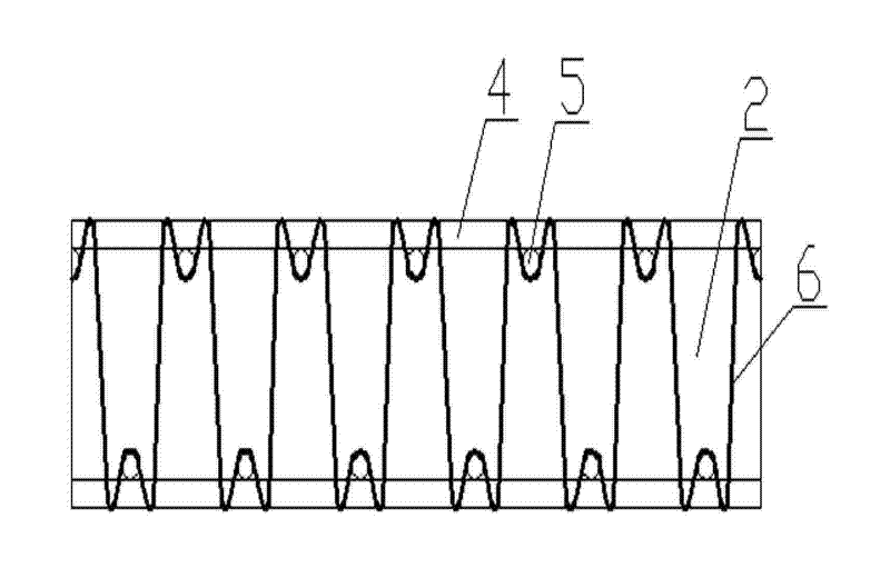
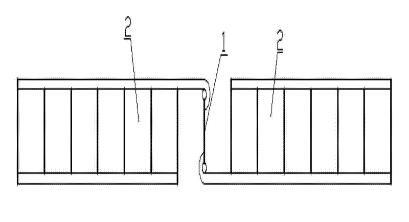
[0022] Such as figure 1 As shown, the steel mesh partition wall of the present invention is composed of a structural column 1 and one or more mesh sheets 2, and the mesh sheet 2 and the structural column 1 are connected into one body through a positioning piece 7, and the positioning piece 7 is a U Type structure, the two legs of the positioning piece 7 are inclined inward, and the horizontal angle with the positioning piece 7 is less than 90 degrees, there is a concave in the center of the positioning piece 7, and the meshes 2 are connected into one body through the structural column 1, and the steel mesh The surface 3 and the frame constitute the mesh 2, and there is foam concrete in the middle of the mesh 2, the steel mesh surface 3 is located on the outer surface of the frame, the stressed gluten 4, the stressed tendon 5 and the support frame 6 form the frame, and the support frame 6 is continuous W-shaped, there is a concave at the top of the W-shaped, and the parallel st...

Embodiment 2

[0024] A method for installing a steel mesh partition wall as described in Embodiment 1, the steps are as follows:

[0025] a. Use the steel bar welding machine to make the steel bar into the mesh;

[0026] b. The structural column, the mesh and the mesh are fixed with a positioning piece;

[0027] c. Use a grouting machine to inject concrete into the structural column, and fill it up after vibration;

[0028] d. After the wall is filled, use a spraying machine to spray, paint and smooth the whole wall. After at least 4 to 5 days of self-drying, use a grouting machine to inject foam concrete into the hollow of the mesh;

[0029] e. After foaming, it becomes porous, and the installation is completed after solidification and molding.

[0030] The foam concrete is any one of polyurethane foam, polystyrene foam, aerated concrete and fiber concrete.


PUM


Abstract

The invention discloses a steel-mesh separation wall and relates to a wall body for a building, in particular to integral seismic resistant wall bodies inside and outside the building. The steel-mesh separation wall comprises construction columns and one or more mesh pieces; the mesh pieces are connected to form a whole by using the construction columns; steel mesh surfaces and frameworks form the mesh pieces; foam concrete is arranged in the mesh pieces; the steel mesh surfaces are positioned on the outer surfaces of the frameworks; stressed surface ribs, stressed ribs and support frames form the frameworks; the support frames are of a continuous W shape; the top ends of the W shape are inwards concaved; the mutually-parallel stressed ribs are respectively positioned in the inner concaves of the continuous W shape and are fixedly connected with the support frames; the stressed surface ribs are mutually perpendicular to the stressed ribs; one side of each stressed surface rib is fixedly connected with the corresponding steel mesh surface; and the other side of each stressed surface rib is fixedly connected with the corresponding stressed rib. The stell-mesh separation wall disclosed by the invention has the advantages of convenience for mounting, simpleness for construction and strong seismic resistant capability.

Description

technical field [0001] The invention relates to a building wall, in particular to an integral anti-seismic wall inside and outside the building. Background technique [0002] The invention patent with the Chinese patent application number 200820081716.9 discloses a steel grid wall, which is composed of a wall panel unit and a female column. The frame welded by transverse and longitudinal bars perpendicular to each other is covered with grid sheets respectively, and the four peripheries of the two grid sheets are butted around the frame, and the interlayer between the two frames is fixedly connected with W-shaped steel bars, W The steel bars are arranged in parallel in the same direction. However, in the process of transport and installation of this technical solution, the transverse ribs and longitudinal ribs are easy to fall off and deform during the welding process, which makes the quality of construction and installation irregular. Contents of the invention [0003] T...

Claims


Application Information

Patent Timeline
IPC IPC(8): E04B2/56E04G21/00
Inventor 刘德政刘云龙吴云辉
Owner 刘德政
Why Eureka
Try Eureka