Air intake pressure stabilizing device of sequential supercharged diesel engine and control method thereof

A stable control method and sequential supercharging technology, applied in electrical control, engine control, fuel injection control, etc., can solve problems such as unstable operation, reduced exhaust gas flow rate of the basic turbocharger, and speed fluctuations, so as to improve the overall quality, The smooth effect of successive booster switching process

Inactive Publication Date: 2013-03-06
HARBIN ENG UNIV
View PDF6 Cites 0 Cited by
  • Summary
  • Abstract
  • Description
  • Claims
  • Application Information

AI Technical Summary

Problems solved by technology

However, because the air valve lags behind the opening of the gas valve, the exhaust gas flow rate of the basic supercharger decreases instantaneously, and the supercharged air flow rate and pressure ratio provided by it decrease, but the controlled supercharger cannot provide supercharged air to the engine, resulting in The air-fuel ratio of the engine decreases and increases instantaneously before and after the switching process, the speed fluctuates sharply, and the operation is not stable
If the supercharging system does not cooperate well with the engine or the switching control is improper, the compressor is likely to enter the surge region and the engine may be subjected to a large thermal shock
[0004] At present, there is no relevant report on "adding compressed air to the engine intake manifold to improve the process of sequential boost switching"

Method used


Image

  • Air intake pressure stabilizing device of sequential supercharged diesel engine and control method thereof
  • Air intake pressure stabilizing device of sequential supercharged diesel engine and control method thereof

Examples


Embodiment Construction

[0019] The present invention is described in more detail below in conjunction with accompanying drawing example:

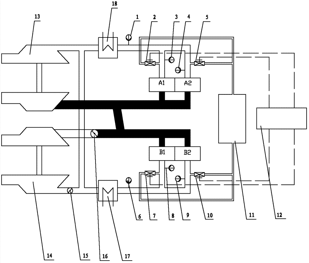
[0020] combine Figure 1~2 , the air intake pressure stabilizing device for successive supercharged diesel engines of the present invention, the turbocharger is connected with the cylinder of the diesel engine through a pipeline, the intercooler is installed on the pipeline connecting the compressor of the turbocharger with the cylinder of the diesel engine, the compressed air source 11 is connected with each The intake manifold of each diesel engine cylinder is connected, the outlet of the intercooler and the intake manifold of the diesel engine cylinder are equipped with pressure sensors, the intake manifold of the diesel engine cylinder is also equipped with a solenoid valve, and the intake pressure controller 12 is connected with the pressure sensor and the solenoid valve. There are two turbochargers, two intercoolers, intercooler 17 and intercooler 18, four d...


PUM


Abstract

The invention aims to provide an air intake pressure stabilizing device of a sequential supercharged diesel engine and a control method thereof. The air intake pressure stabilizing device provided by the invention comprises diesel engine cylinders, a turbocharger, an intercooler, pressure sensors, electromagnetic valves, an air valve, a gas valve, a compressed air source and an air intake pressure controller, wherein the turbocharger is connected with the diesel engine cylinders through a pipeline; the intercooler is installed on a pipeline on which the gas compressor of the turbocharger is connected with the diesel engine cylinders; the compressed air source is connected with the air intake manifold of each diesel engine cylinder; the pressure sensors are installed on the outlet of the intercooler and the air intake manifolds of the diesel engine cylinders; the electromagnetic valves are also installed on the air intake manifolds of the diesel engine cylinders; and the air intake pressure controller is connected with the pressure sensors and the electromagnetic valves. The device and method provided by the invention can be used for carrying out the air intake supplementation on the air intake pipe of the diesel engine in the switching course, thereby maintaining the air intake pressure unchangeable, enable the sequential supercharged switching course to be more stable and arebeneficial to the enhancement for the overall quality of the engine.

Description

technical field [0001] The invention relates to an engine intake and exhaust control device and method. Background technique [0002] Successive supercharging technology was first adopted by MTU in West Germany in the late 1970s. Its design is mainly to expand the working range of low compression ratio and high supercharging engines, increase the low-speed torque of the engine and reduce the operating time of part load. fuel consumption rate. Its basic principle is to use multiple turbochargers, which are sequentially put into operation as the engine speed and load increase, so as to ensure that the working turbochargers are always running in the high-efficiency zone, so that the engine's The fuel consumption rate is low throughout the operating range, and the low-speed high-torque performance is good. [0003] During the switching process of successive boosting of the diesel engine, the gas valve and the air valve are opened successively, and the controlled supercharger i...

Claims


Application Information

Patent Timeline
Patent Type & Authority Patents(China)
IPC IPC(8): F02B37/12F02M35/10F02M35/104F02B37/00F02B29/04F02D41/04F02D23/00
CPCY02T10/12
Inventor 王银燕何清林杨传雷王贺春冯永明张鹏奇
Owner HARBIN ENG UNIV
Why Eureka
Try Eureka