Magneto-optic Kerr effect and magnetocrystalline anisotropy field measurement system and measurement method

A technology of magnetic crystal anisotropy and magneto-optical Kerr effect, applied in the field of physical measurement, can solve the problem of mechanical vibration, stepping motor rotating magnetic field takes a long time, affects the measurement accuracy of magneto-optical Kerr effect and magneto-optic Kerr effect issues with measurement efficiency

Inactive Publication Date: 2011-11-23
FUDAN UNIV
View PDF7 Cites 17 Cited by
  • Summary
  • Abstract
  • Description
  • Claims
  • Application Information

AI Technical Summary

Problems solved by technology

[0003] At present, the magnetic field of this type of device mainly uses a stepping motor to drive the magnet to achieve rotation. It can perform basic measurements of the magneto-optical Kerr effect and the magnetocrystalline anisotropy field, but there are great shortcomings, such as: The rotation of the magnet driven by the stepping motor inevitably introduces mechanical vibration, which brings a lot of noise to the measurement results; it takes a long time to rotate the magnetic field with the stepping motor, which makes the sample more affected by the environment; Drift occurs in the measurement of , making the measurement results inaccurate
Such problems in existing devices have greatly affected the measurement accuracy and efficiency of the magneto-optical Kerr effect and magnetocrystalline anisotropy field

Method used


Image

  • Magneto-optic Kerr effect and magnetocrystalline anisotropy field measurement system and measurement method
  • Magneto-optic Kerr effect and magnetocrystalline anisotropy field measurement system and measurement method
  • Magneto-optic Kerr effect and magnetocrystalline anisotropy field measurement system and measurement method

Examples


Embodiment Construction

[0021] 1. Theoretical basis of the measurement system

[0022] 1. Surface magneto-optical Kerr effect (SMOKE) principle:

[0023] When linearly polarized light is reflected by a magnetic medium, the plane of polarization and ellipticity will change. This effect is called the magneto-optical Kerr effect. The study of the magneto-optic Kerr effect on surfaces and ultra-thin films is called Surface Magneto-Optic Kerr Effect (SMOKE).

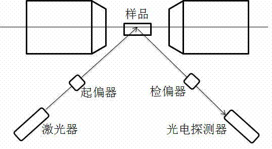
[0024] like image 3 , the magneto-optical Kerr effect is the effect caused by the off-diagonal elements of the dielectric tensor of the material when light passes through the material. In essence, it is the effect caused by the coupling of light and electron spin-orbit coupling in the magnetic medium during the propagation process. A beam of p-light is reflected by the sample. When the sample is non-magnetic, the reflected light is also p-light. When the sample is magnetic, the reflected light will contain the p-light component (E p ) and a sma...


PUM


Abstract

The invention belongs to the technical field of physical measurement, and in particular relates to a magneto-optic Kerr effect and magnetocrystalline anisotropy field measurement system and a measurement method. The measurement system comprises a magnet control part and a laser detection part. The magnet control part mainly comprises a magnet bracket, power supplies, an ADDA (analog-digital and digital-analog) card and a computer, wherein the computer respectively controls the size and the direction of output current of the two power supplies through the ADDA card, and respectively controls the size and the direction of magnetic fields so as to obtain a required resultant magnetic field; and the laser detection part is composed of a laser device, a polarizer, a polarization analyzer, a photoelectric detector, an ADDA card and a computer, wherein laser emitted by the laser device is projected to the photoelectric detector after being filtered by the polarizer and the polarization analyzer, signals are transmitted to the computer after being converted by the ADDA card, and then Kerr signals of a detection point are obtained. According to the measurement system and the measurement method, the mechanical vibration can be eliminated, the noise in the measurement can be reduced, the accuracy of the measurement can be increased, and magnetic signals and the magnetocrystalline anisotropy field of a sample can be accurately and efficiently obtained.

Description

technical field [0001] The invention belongs to the technical field of physical measurement, and in particular relates to a surface magneto-optical Kerr effect and magnetocrystal anisotropy field measurement device and measurement method. Background technique [0002] Measuring the magneto-optical Kerr effect and magnetocrystalline anisotropy field of matter is the basic detection method in the field of thin film magnetism research. The measurement device requires a rotatable magnetic field: in the measurement of the magneto-optical Kerr effect (MOKE method) , it is necessary to rotate the magnetic field to find a suitable magnetization direction; when measuring the magnetocrystalline anisotropy field (ROTMOKE method), it is necessary to rotate the magnetic field 360° and measure the Kerr signal of each magnetic field direction. [0003] At present, the magnetic field of this type of device mainly uses a stepping motor to drive the magnet to achieve rotation. It can perform ...

Claims


Application Information

Patent Timeline
Patent Type & Authority Applications(China)
IPC IPC(8): G01N21/21G01R33/12
Inventor 梁建辉武迪胡春瑞刘方泽吴义政
Owner FUDAN UNIV
Why Eureka
Try Eureka