
Oscillation circuit

一种振荡电路、振荡器的技术,应用在功率振荡器、电脉冲发生器电路、电气元件等方向,能够解决电路结构复杂、加快振荡电路部等问题

Inactive Publication Date: 2011-11-23
PANASONIC CORP
View PDF6 Cites 0 Cited by
  • Summary
  • Abstract
  • Description
  • Claims
  • Application Information

AI Technical Summary

Problems solved by technology

[0007] This method is an effective means to speed up the start-up of the oscillation circuit section, but there is a problem that the circuit configuration becomes complicated by providing a ring oscillator including a current source having a temperature correction function, etc.
[0009] However, in the above configuration, in order to provide a pulse from the outside to the oscillation circuit section at the initial stage of startup of the oscillation circuit section to speed up startup of the oscillation circuit section, a ring oscillator including a current source with a temperature correction function is provided, so there is a circuit structure complicated question

Method used


Image

  • Oscillation circuit
  • Oscillation circuit
  • Oscillation circuit

Examples


Embodiment approach

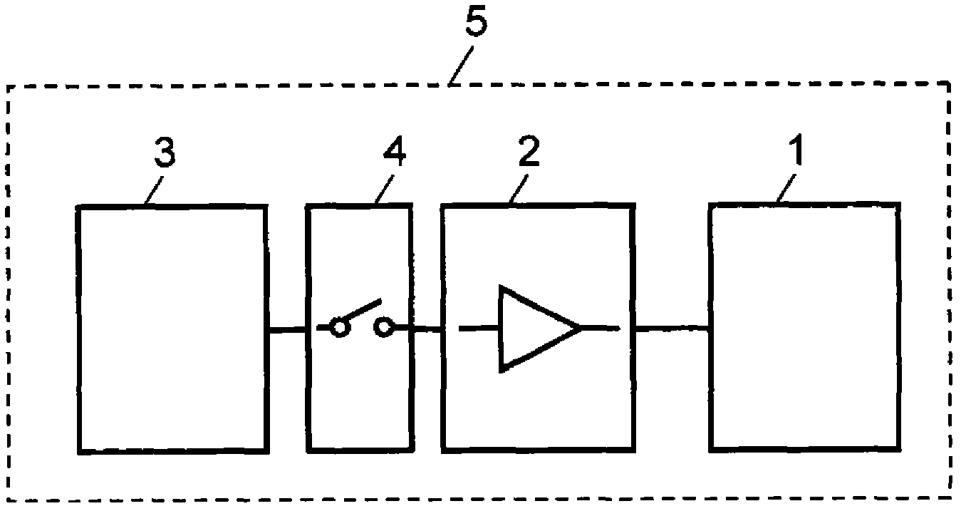
[0022] figure 1 It is a block diagram of an oscillation circuit according to an embodiment of the present invention. exist figure 1 Among them, the oscillation circuit 5 includes an oscillator 1 , an amplifier 2 , an excitation pulse generation unit 3 for generating an Energizing Pulse (Energizing Pulse), and a switching unit 4 . Here, the switching unit 4 switches between connection and disconnection between the excitation pulse generation unit 3 and the oscillator 1 , and between the excitation pulse generation unit 3 and the amplifier 2 . In addition, the oscillation circuit 5 is equipped with figure 1 An operation command unit not shown in the figure, the operation command unit sends a command signal to start operation to the oscillator 1 , the amplifier 2 , the excitation pulse generation unit 3 , and the switching unit 4 . The operation instruction unit is composed of a microcomputer.

[0023] As the oscillator 1, a crystal oscillator or a ceramic oscillator, or a cr...


PUM


Abstract

An oscillation circuit comprises an oscillator, further comprising a resonance frequency, an amplifier that is connected to the oscillator, an energized pulse emission unit, which emits a pulse of a frequency, from among the resonance frequency, which falls within a given range, a switching unit, which switches between the energized pulse emission unit being connected to, and disconnected from, the oscillator and the amplifier, and an operation instruction unit, which issues an instruction signal to the energized pulse emission unit to commence operating, wherein the switching unit connects the oscillator and the energized pulse emission unit during an interval that commences at the time that the operation instruction unit issues the operation instruction, the interval comprising one cycle, half a cycle, or a plurality of cycles of pulses that the energized pulse emission unit emits.

Description

technical field [0001] The present invention relates to an oscillation circuit that shortens the time from driving to oscillation stabilization of an oscillation circuit using an oscillator. Background technique [0002] Devices using batteries generally require power saving. For example, an ultrasonic flowmeter using a battery operates intermittently within the range allowed by flow measurement accuracy in order to save power. The ultrasonic flowmeter measures the propagation time of ultrasonic waves to obtain the flow velocity, and calculates the flow rate by multiplying the flow velocity by the cross-sectional area of ​​the pipe. Ultrasonic propagation time measurement uses pulses with a fixed period, counts the number of pulses from the transmission of ultrasonic waves to the reception of ultrasonic waves, and multiplies the number of pulses by the pulse cycle to obtain the propagation time of ultrasonic waves. When intermittent flow measurement is performed, it is of ...

Claims


Application Information

Patent Timeline
Patent Type & Authority Applications(China)
IPC IPC(8): H03B5/32H03B5/02H03B5/20H03K3/02
CPCH03B5/06H03K3/0307H03B5/30H03K3/014G01F1/667
Inventor 别荘大介
Owner PANASONIC CORP
Learn More