
Hydraulic machine

A technology of hydraulic presses and hydraulic cylinders, applied in the field of hydraulic presses with high and low pressure automatic conversion, which can solve the problems of inability to adjust hydraulic pressure, inconvenience for staff to carry, increase in weight and volume, and achieve compact structure, enhanced function diversity, and improved use. The effect of longevity

Active Publication Date: 2014-04-09
大有国华(重庆)科技发展有限公司
View PDF8 Cites 0 Cited by
  • Summary
  • Abstract
  • Description
  • Claims
  • Application Information

AI Technical Summary

Problems solved by technology

[0002] As we all know, the hydraulic machine supplies the hydraulic oil in the oil tank to the hydraulic cylinder through the oil pump, and the hydraulic cylinder drives the hydraulic actuator to work. However, when the hydraulic machine is used in different occasions, its flexibility requirements are higher. Most hydraulic machines are very rigid. , the hydraulic pressure cannot be adjusted reasonably according to actual needs, and its pressure adjustment range is very narrow, which is not suitable for the actual needs of work. However, with the advancement of science and technology, hydraulic presses that can realize high-low pressure conversion have appeared one after another. The sequence valve or shift switch on the hydraulic machine can be adjusted according to the actual load to achieve the actual required pressure. For example, low pressure is used for normal feeding, and it is converted to a high-pressure output state as the load increases when the hydraulic machine is required to exert force. This solves the problem of use under high load conditions, especially when the hydraulic press is used for crushing, cutting, punching, bending, fastening, etc., a hydraulic press that can carry high loads is required. However, the usual hydraulic press that can realize high and low pressure conversion The high and low pressure conversion must be done through additional sequence valves or other conversion mechanisms. The structure is quite complicated and requires the actual experience of the operator to adjust the pressure of the hydraulic press and its high and low pressure conversion. The level of automation is not high. At the same time, To achieve high-pressure output and low-pressure output, the usual hydraulic machine needs two hydraulic pumps to complete, and the two hydraulic pumps will also increase the transmission mechanism for power transmission, which further increases the overall structure of the hydraulic machine. Not only the weight and volume increase, but also the It is easy for the staff to carry, and it causes the cost of the hydraulic machine to increase, which is not conducive to actual use; secondly, the hydraulic machine has a wide range of applications, and different execution tools need to be used in different areas of use, so there have been various hydraulic presses for the implementation of tooling, but the existing The execution tooling of the hydraulic press is usually fixed and lacks interchangeability. In the actual work, the staff will carry a variety of hydraulic tools when performing a task, resulting in a reduction in the efficiency of the staff performing the task; again, the usual hydraulic press The speed of the oil pump is limited by the speed range of the drive motor itself, which cannot flexibly meet the needs of use; and the hydraulic machine is mostly used for outdoor work, which lacks a power source for outdoor work. When working outdoors, it sometimes fails to work, which seriously affects the work. Progress, and finally, the oil tank of the hydraulic machine usually adopts a rigid oil tank, which not only increases the weight of the hydraulic machine, but also is prone to oil spills

Method used


Image

  • Hydraulic machine
  • Hydraulic machine
  • Hydraulic machine

Examples


Embodiment Construction

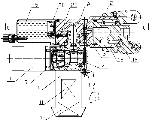
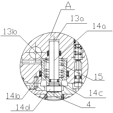
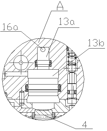
[0020] Such as Figure 1 to Figure 7 As shown, a hydraulic machine includes a housing 10, a drive motor 1, an oil pump, an oil tank 5, and a hydraulic cylinder 2. The oil pump driven by the drive motor 1 is a plunger pump, and the output shaft of the drive motor 1 is connected to a planetary gear transmission 3 The power input shaft of the planetary gear transmission 3 and the power output shaft of the planetary gear transmission 3 are connected to the camshaft 4 of the plunger pump. The camshaft 4 is provided with a plunger 14 that can perform piston movement in the pump chamber 13, and the camshaft 4 and the plunger 14 form a cam Tappet mechanism, its pump cavity 13 top is set as high-pressure cavity 13a, and pump cavity 13 bottom is set as low-pressure cavity 13b, and the cross-sectional radius of low-pressure cavity 13b is greater than the cross-sectional radius of high-pressure cavity 13a, and the plunger in described pump cavity 13 14 According to the size of the high an...


PUM


Abstract

The invention discloses a hydraulic machine. The hydraulic machine comprises a shell, a drive motor, an oil pump, an oil tank and a hydraulic cylinder, wherein the oil pump is a plunger pump; an output shaft of the drive motor is connected with a camshaft of the plunger pump; a cam tappet rod mechanism is formed by the camshaft and a plunger; the upper part of a pump cavity of the plunger pump is provided with a high-pressure cavity, and the lower part of the pump cavity is provided with a low-pressure cavity; the cross section radius of the low-pressure cavity is greater than that of the high-pressure cavity; the plunger in the pump cavity is provided with a boss structure which has the same size as the high-pressure cavity and the low-pressure cavity of the pump cavity; the upper parts of the high-pressure cavity and the low-pressure cavity are provided with oil inlet and outlet holes; and the oil inlet and outlet holes of the high-pressure cavity and the low-pressure cavity are connected with the oil tank through respective oil inlet circuits in which oil inlet one-way valves are arranged, and are connected with the hydraulic cylinder through respective oil outlet circuits in which oil outlet one-way valves are arranged. The hydraulic machine can supply oil through a high-pressure oil circuit and a low-pressure oil circuit simultaneously, automatically switches high pressure and low pressure according to different loads, and has a simple integral structure and multiple functions.

Description

technical field [0001] The invention relates to a hydraulic machine, in particular to a hydraulic machine with automatic switching between high and low pressure. Background technique [0002] As we all know, the hydraulic machine supplies the hydraulic oil in the oil tank to the hydraulic cylinder through the oil pump, and the hydraulic cylinder drives the hydraulic actuator to work. However, when the hydraulic machine is used in different occasions, its flexibility requirements are higher. Most hydraulic machines are very rigid. , the hydraulic pressure cannot be adjusted reasonably according to actual needs, and its pressure adjustment range is very narrow, which is not suitable for the actual needs of work. However, with the advancement of science and technology, hydraulic presses that can realize high-low pressure conversion have appeared one after another. The sequence valve or shift switch on the hydraulic machine can be adjusted according to the actual load to achiev...

Claims


Application Information

Patent Timeline
Patent Type & Authority Patents(China)
IPC IPC(8): B30B1/32
Inventor 王军
Owner 大有国华(重庆)科技发展有限公司
Learn More