
High-speed UV light curing control device for printing press

A printing machine and control device technology, which is applied to printing machines, general parts of printing machinery, printing, etc., can solve the problems of inconvenience, current impact damage to UV lamps, etc., to improve economic benefits, ensure normal work, and avoid shocks Effect

Active Publication Date: 2011-11-30
GUANGDONG LONGXING PACKAGING IND
View PDF6 Cites 15 Cited by
  • Summary
  • Abstract
  • Description
  • Claims
  • Application Information

AI Technical Summary

Problems solved by technology

Furthermore, the power of the lamp needs to be increased step by step during the start-up process. Full power conduction in the cold state will cause excessive current impact and damage the UV lamp.
[0003] This shows that in the structure and use of above-mentioned existing UV curing machine, obviously still have inconvenience and defective, and urgently need to be further improved

Method used


Image

  • High-speed UV light curing control device for printing press
  • High-speed UV light curing control device for printing press
  • High-speed UV light curing control device for printing press

Examples


Embodiment 1

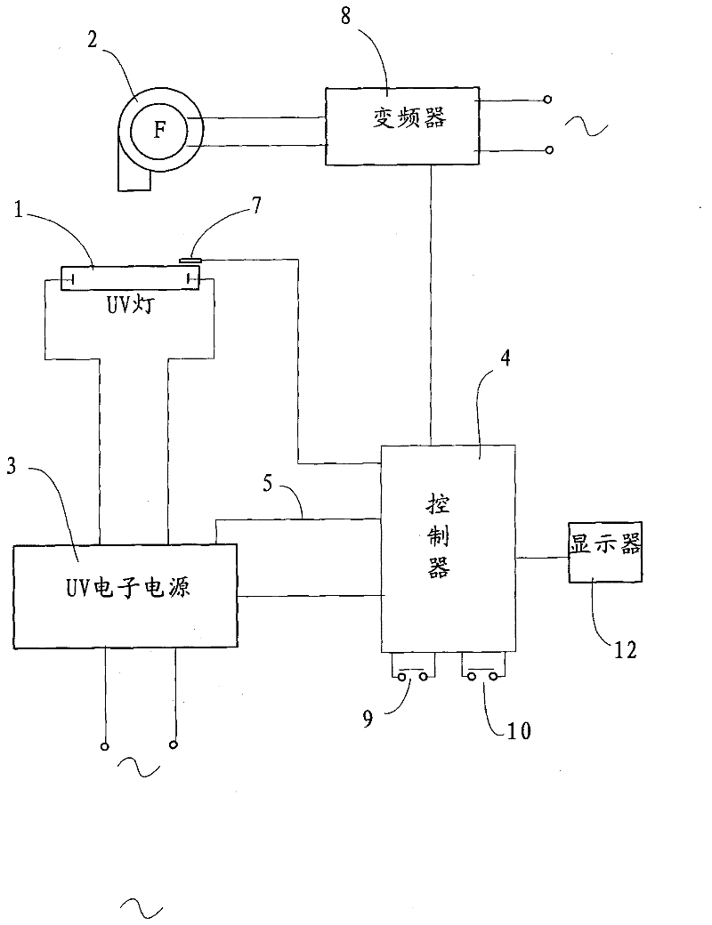
[0025] see figure 1 As shown, the high-speed UV photocuring control device for a printing machine in a preferred embodiment of the present invention includes a UV lamp 1 with a condenser, a fan 2, a UV electronic power supply 3 with a fault detection signal line 5, and a controller 4, wherein The output terminal of the UV electronic power supply is connected to the UV lamp 1, and its fault detection signal line 5 is connected to the controller 4; a temperature sensor 7 is arranged in the illumination area of ​​the UV lamp 1, and the temperature sensor 7 is electrically connected to The controller 4 is provided with a frequency converter 8, the output terminal of the frequency converter 8 is connected to the fan 2, the input control terminal of the frequency converter 8 is connected to the controller 4, and the input terminal of the controller 4 A start button 9 and a power reduction button 10 are provided, and the output terminals of the controller 4 are respectively connected...

Embodiment 2

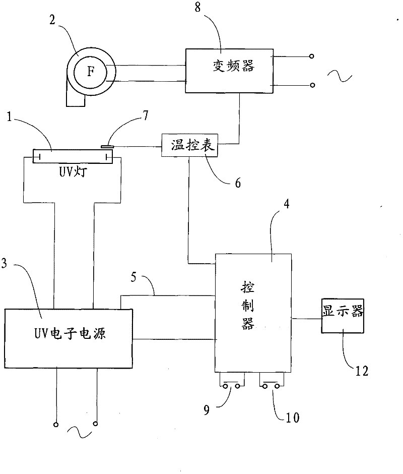
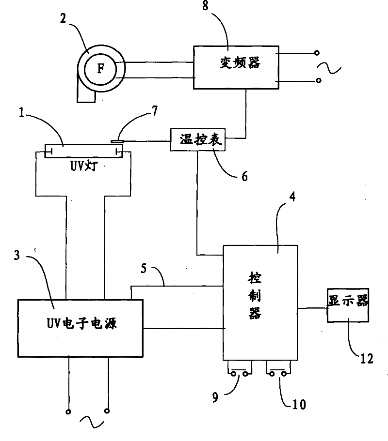
[0032] see figure 2 As shown, the high-speed UV photocuring control device for printing presses in another preferred embodiment of the present invention includes a UV lamp 1 with a condenser, a fan 2, a UV electronic power supply 3 with a fault detection signal line 5, and a controller 4 , wherein a frequency converter 8 and a temperature controller 6 are provided, the output terminal of the UV electronic power supply 3 is connected to the UV lamp 1, and its fault detection signal line 5 is connected to the controller 4; the illumination area of ​​the UV lamp 1 There is a temperature sensor 7 inside, the temperature sensor 7 is electrically connected to the thermostat 6, the output of the thermostat 6 is respectively connected to the controller 4 and the frequency converter 8, and the output of the frequency converter 8 The terminal is connected to the fan 2 , the input of the controller 4 is provided with a start button 9 and a power reduction button 10 , and the output of t...


PUM


Abstract

The invention relates to light curing equipment and particularly relates to a high-speed UV (ultraviolet) light curing control device which comprises a UV lamp provided with a spotlight cover, a fan, a UV electronic power supply provided with a fault detection signal wire, a controller and a frequency converter, wherein the output end of the UV electronic power supply is connected with a UV lamp, and the fault detection signal wire of the UV electronic power supply is connected with the controller; the illumination region of the UV lamp is provided with a temperature sensor which is electrically connected with the controller; the output end of the frequency converter is connected with the fan; and the input end of the controller is at least provided with a start button and a power-reducing button, and the output end of the controller is respectively connected with the UV electronic power supply and the control end of the frequency converter. The novel device provided by the invention can be used for realizing the automation of the temperature control and on-off control on a light curing device, thus the printing quality and the printing efficiency are further ensured.

Description

technical field [0001] The invention relates to a photocuring device, in particular to a high-speed UV photocuring control device for a printing machine. Background technique [0002] At present, the printing and ink of the printing machine are cured by UV light curing equipment. UV light curing equipment is the key equipment to ensure the printing quality. A typical UV light curing equipment is composed of a light source system, a cooling system and a control system. The light source system includes UV Lamp, lampshade, UV electronic power supply (or trigger, ballast); most of the cooling systems are air-cooled. If the air volume is too small and the cooling is insufficient, the temperature of the UV lamp will be too high and the life of the lamp will be shortened. It also makes the cured product wrinkle, and the quality is difficult to guarantee; if the air volume is too large and the cooling is excessive, the temperature of the UV lamp will be too low, the UV lamp cannot w...

Claims


Application Information

Patent Timeline
IPC IPC(8): B41F23/04B41F33/16
Inventor 王贤淮
Owner GUANGDONG LONGXING PACKAGING IND
Learn More