
Hybrid power system

A hybrid power system and engine technology, applied in the direction of charging system, engine components, combustion engine, etc., can solve the problems of power system efficiency drop, compressed air energy loss, ice blockage, etc., to increase the power per liter, shorten the starting time, The effect of reducing the air expansion ratio

Active Publication Date: 2013-09-18
SAIC MOTOR
View PDF5 Cites 2 Cited by
  • Summary
  • Abstract
  • Description
  • Claims
  • Application Information

AI Technical Summary

Problems solved by technology

Cars powered by compressed air at home and abroad have the following problems: During use, due to the expansion of high-pressure air, a large amount of heat needs to be absorbed, and the low-temperature exhaust of the air-driven engine will cause condensation and ice blockage when the heat exchange is insufficient. Phenomenon; high-pressure compressed air is decompressed before entering the air motor, which causes energy loss of compressed air in the process
These reasons will lead to a decrease in the efficiency of the power system
The "compressed air-fuel / gas hybrid vehicle engine" disclosed in Chinese patent 02111984.8 and the "hybrid engine" disclosed in Chinese patent 200720107832 use engine exhaust to heat the compressed air intake, which can improve the efficiency of the pneumatic engine to a certain extent and relieve condensation. However, there are still certain limitations in the cooperation between the pneumatic engine and the engine in the above system, and it has not shown sufficient interoperability in operating conditions, and it still cannot solve the self-filling and storage requirements of compressed air. Problems with very high storage pressure
This series of problems makes it difficult for pure pneumatic systems to become practical

Method used


Image

  • Hybrid power system
  • Hybrid power system

Examples


Embodiment Construction

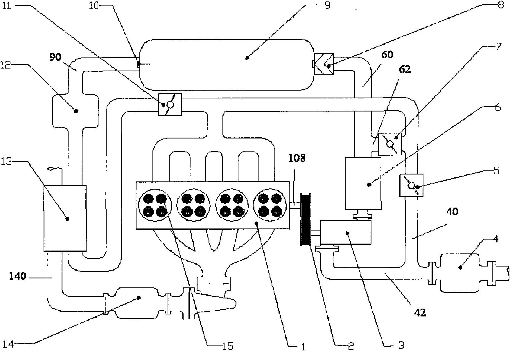
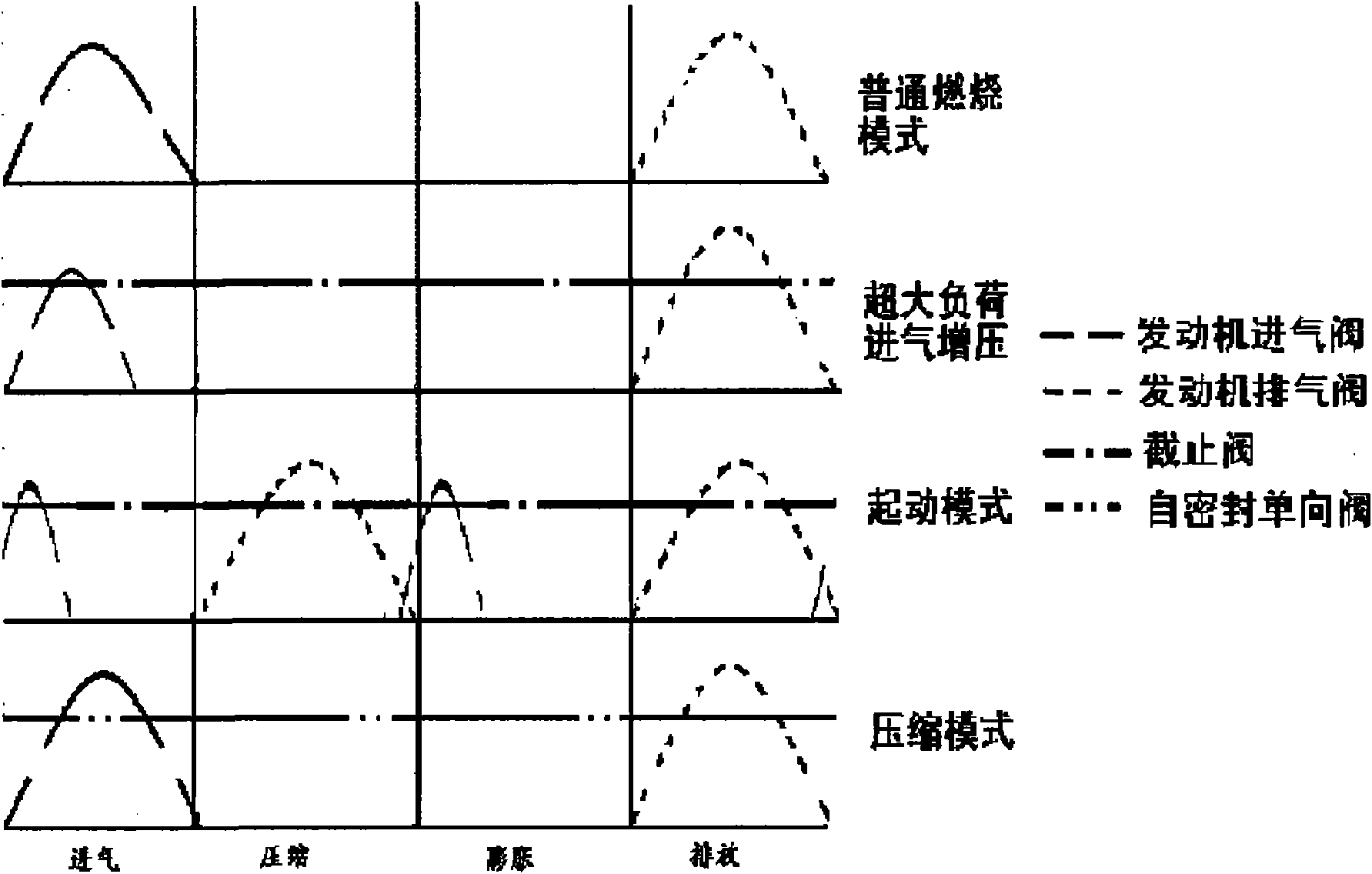
[0032] Figure 1-2 The following description describes specific embodiments of the invention to teach those skilled in the art how to make and use the best mode of the invention. In order to teach inventive principles, some conventional aspects have been simplified or omitted. Those skilled in the art will appreciate that variations from these examples fall within the scope of the invention. Those skilled in the art will appreciate that the features described below can be combined in various ways to form multiple variations of the invention. As a result, the invention is not limited to the specific embodiments described below, but only by the claims and their equivalents.

[0033] An embodiment of the present invention provides a low-cost variable supercharging air hybrid power system with waste heat utilization, which combines the characteristics of the engine power system and the aerodynamic system, and can realize the idling condition in a short time functions such as fast...


PUM


Abstract

The invention provides a hybrid power system. The system comprises an engine, first and second intake pipelines, first and second compressed air pipelines, a high pressure air pipeline and a heat exchanger, wherein the first and second intake pipelines are connected with each other in parallel and are connected with a main air intake in series via an air filter; the first air intake pipeline is connected with the engine in series; the first and second compressed air pipelines are connected with each other in parallel and are connected with a compressor in series via an intercooler; the secondcompressed air pipeline is connected with the first air intake pipeline in series; the high pressure air pipeline is connected with the first compressed air pipeline in series via a gas storage tank and is connected with the engine in series; the heat exchanger is arranged on the high pressure air pipeline; and the high pressure air pipeline is arranged adjacent to an engine exhaust pipeline in the heat exchanger so as to heat the high pressure gas from the gas storage tank, thus reducing the occurrence of ice barrier on an exhaust pipe caused by too low intake temperature and energy loss brought about by expansion of air in a cylinder under the starting condition.

Description

【Technical field】 [0001] The present invention relates to hybrid powertrains. Specifically, the present invention relates to a variable supercharging hybrid power system with exhaust waste heat utilization. 【Background technique】 [0002] The fuel economy of the engine is poor when the engine is running under light load conditions, especially for vehicles traveling under urban road conditions with multiple idle speeds and low speeds, the fuel consumption per 100 kilometers will increase significantly. To cancel the engine idling condition to improve fuel economy, the engine is required to be able to achieve quick stop / start in a short period of time. At present, the small engines used in vehicles are mostly driven by the starter motor to start. Since the power of the starter motor is small and the dragging speed is low, the engine must use open-loop control to control the fuel injection in the first few ignition and combustion cycles of the engine, which leads to fuel consu...

Claims


Application Information

Patent Timeline
Patent Type & Authority Patents(China)
IPC IPC(8): F02B41/00F02G5/02F02M31/08F02B29/04
CPCY02T10/146Y02T10/166Y02T10/12
Inventor 邵强张华张小红孔毅
Owner SAIC MOTOR
Learn More