A separate cooling led lamp

An LED lamp, a separate technology, applied in lighting and heating equipment, components of lighting devices, cooling/heating devices of lighting devices, etc., can solve the problems of increased weight of LED lights, complicated structure of LED lights, and increased material costs. , to achieve the effect of improved effect, simple heat dissipation structure and good heat dissipation effect

Inactive Publication Date: 2011-11-30
东莞联通达电路制板有限公司
View PDF7 Cites 4 Cited by
  • Summary
  • Abstract
  • Description
  • Claims
  • Application Information

AI Technical Summary

Problems solved by technology

This kind of fixed-angle LED light, in some cases, when the light source needs to achieve 360° full-angle light emission, this kind of light cannot meet the needs of users
In order to dissipate the heat quickly, the LED lamps in the prior art usually install a heat dissipation carrier under the circuit board to dissipate heat. The carrier is generally made of metal materials. In this way, not only the weight of the LED lamp is significantly increased, but also the LED The structure of the lamp becomes complicated and the material cost increases
For example, a kind of LED lamp of patent No. 200820050115.1, which includes a semiconductor cooling sheet and an LED lamp group composed of LED lights attached to its cold end. It uses the characteristics of semiconductor cooling sheet to cool at one end and heat at the other end when the current flows through. The heat generated during the lamp operation is dissipated in time, and the hot end of the semiconductor refrigeration sheet is pasted with an aluminum heat sink. Although this method has a good heat dissipation effect, the production is complicated and the cost is high.

Method used


Image

  • A separate cooling led lamp
  • A separate cooling led lamp
  • A separate cooling led lamp

Examples


Embodiment Construction

[0026] Hereinafter, specific embodiments of the present invention will be described in conjunction with the accompanying drawings.

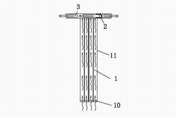
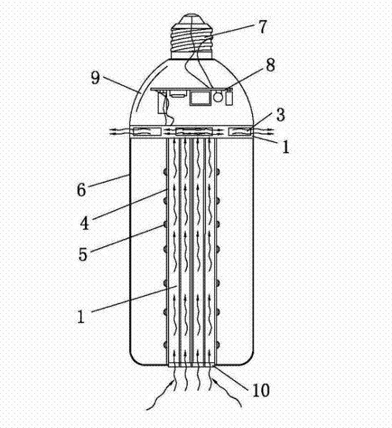
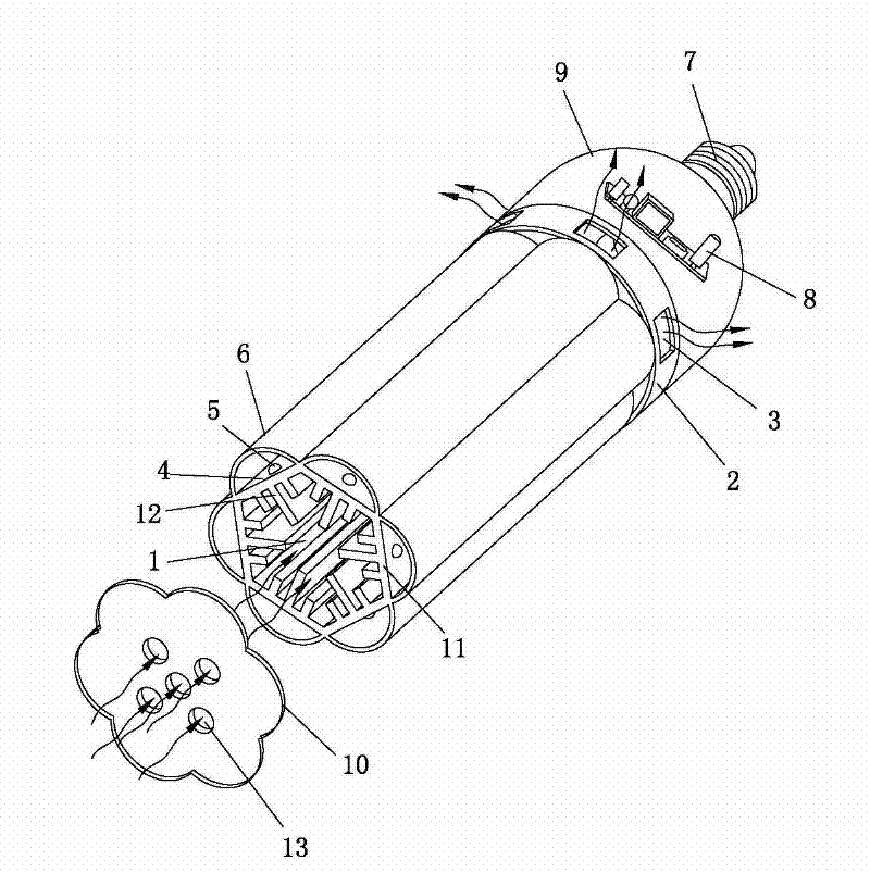
[0027] like Figure 1-Figure 3 As shown, a split heat dissipation LED lamp includes a cylindrical first heat dissipation chamber 1 and a flat box-shaped second heat dissipation chamber 2, one end of the first heat dissipation chamber 1 is connected to the second heat dissipation chamber The chambers 2 are connected and communicated, the second heat dissipation chamber 2 is formed with at least one air hole 3, and the other end of the first heat dissipation chamber 1 has an opening, thereby forming a hollow heat dissipation chamber of the first heat dissipation chamber 1. system and from the opening through the first heat dissipation chamber 1 and then through the second heat dissipation chamber 2 until the air flow out from the vent hole 3; The cavity wall 11 in the longitudinal direction is integrated with the heat dissipation structure 12, an...


PUM


Abstract

The invention provides a separate radiating light emitting diode (LED) lamp and relates to the field of LED lighting. The separate radiating LED lamp comprises a barrel-shaped first radiating chamber and a flat-box type second radiating chamber, wherein one end of the first radiating chamber is connected and communicated with the second radiating chamber; at least one ventilating hole is formed in the second radiating chamber, so that a hollow radiating system of the first radiating chamber and an air flow path where air passes through the first radiating chamber and the second radiating chamber through an opening and flows out of the ventilating hole are formed; a chamber wall of the first radiating chamber along a length direction of the first radiating chamber is integrated with a radiating structure; an LED circuit board is arranged around the chamber wall; LED luminous bodies are arranged on the LED circuit board; a lampshade is arranged; the second radiating chamber is connected and communicated with a power supply chamber provided with a power supply; and the power supply chamber is connected with a lamp holder. The radiating effect is enhanced; the radiating system of the LED luminous bodies is separated from the radiating system of the power supply, so mutual heat interference is avoided; and the electric performance can be improved comprehensively.

Description

technical field [0001] The invention relates to the field of LED lighting, in particular to a separate heat dissipation LED lamp. Background technique [0002] LED lights are a new type of lighting fixtures that have become popular in recent years. In the existing LED lights, the LED light source is generally a direct type, and the light emitting center of the LED luminous body faces the light emitting surface. Due to the limitation of the light emitting angle of the LED luminous body itself, the surrounding area of ​​the LED luminous body is often very bright, and the heat dissipation effect is not good. Easy to fade. [0003] In terms of focusing, in the prior art, a lens is used to focus the LED light, and a reflector is also used to focus the LED light, but basically the angle of light is fixed. This fixed-angle LED light cannot meet the needs of users in some cases when the light source needs to emit light at a full angle of 360°. In order to dissipate the heat quick...

Claims


Application Information

Patent Timeline
Patent Type & Authority Applications(China)
IPC IPC(8): F21S2/00F21V29/00F21V31/00F21Y101/02F21V29/60
Inventor 沈李豪
Owner 东莞联通达电路制板有限公司
Why Eureka
Try Eureka