
Visual inspection system and method capable of resisting sunlight interference

A technology of visual inspection and inspection system, applied in the field of visual inspection, can solve the problems of measurement system ambient light interference, discussion of ambient light interference, changes in reflected light intensity, etc.

Inactive Publication Date: 2011-11-30
上海砺晟光电技术有限公司
View PDF6 Cites 9 Cited by
  • Summary
  • Abstract
  • Description
  • Claims
  • Application Information

AI Technical Summary

Problems solved by technology

[0003] However, in the actual application process, when there is strong ambient light around the sign, especially in an environment with direct sunlight, the traditional visual inspection system will have a big problem: with the increase of the incident angle of sunlight Different, the reflected light intensity of ordinary diffuse reflection signs will change
However, this prior art only gives the measurement principle and system composition, and does not discuss how to resist ambient light interference
From the perspective of the measured object, measurement environment and measurement principle, the measurement system is extremely susceptible to interference from ambient light.

Method used


Image

  • Visual inspection system and method capable of resisting sunlight interference
  • Visual inspection system and method capable of resisting sunlight interference
  • Visual inspection system and method capable of resisting sunlight interference

Examples


Embodiment

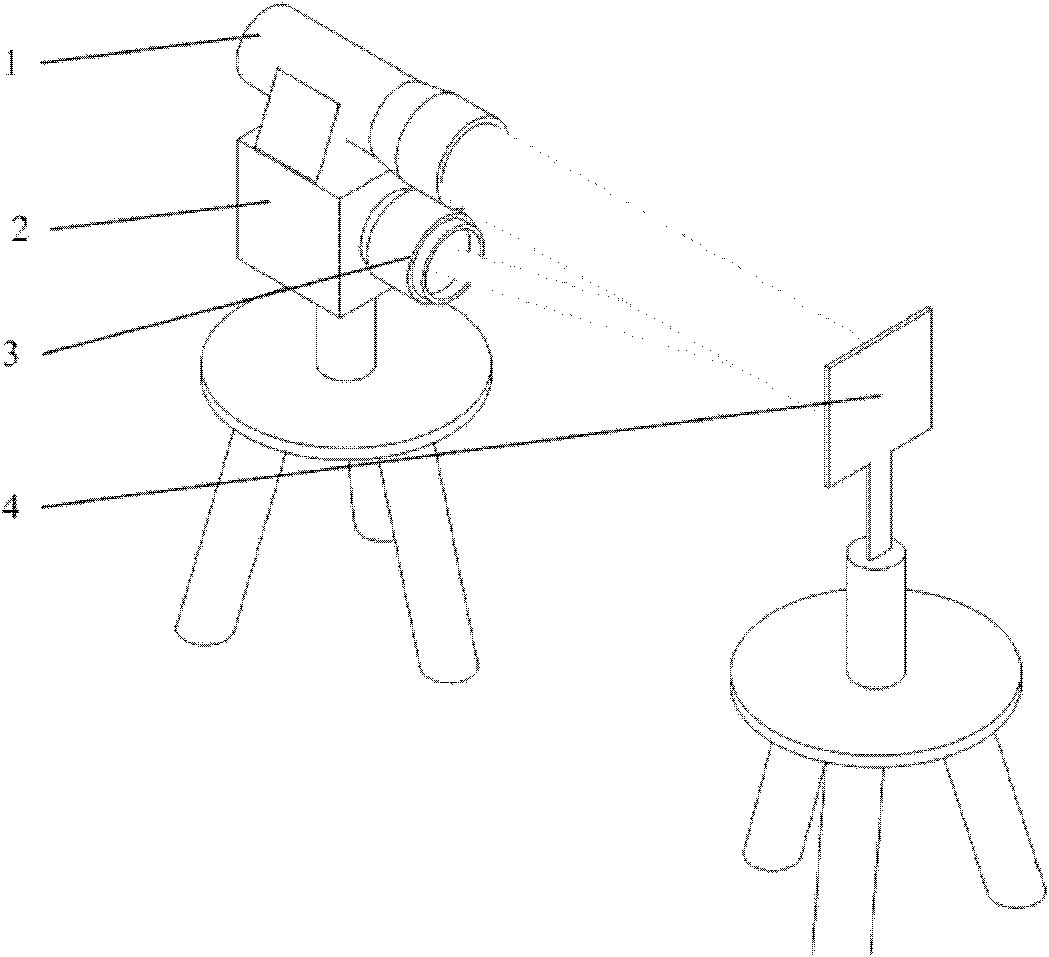
[0034] Such as figure 1 As shown, this embodiment includes: a laser 1, a camera 2, a lens 3, a reflective mark 4, a processing system 8, and an optical filter 9, wherein: the laser 1 and the camera 2 are arranged side by side at the measurement point and are close to each other. Connected to processing system 8. The reflective marker 4 is set on a certain feature point of the measured object 10 and can move together with the measured object 10 .

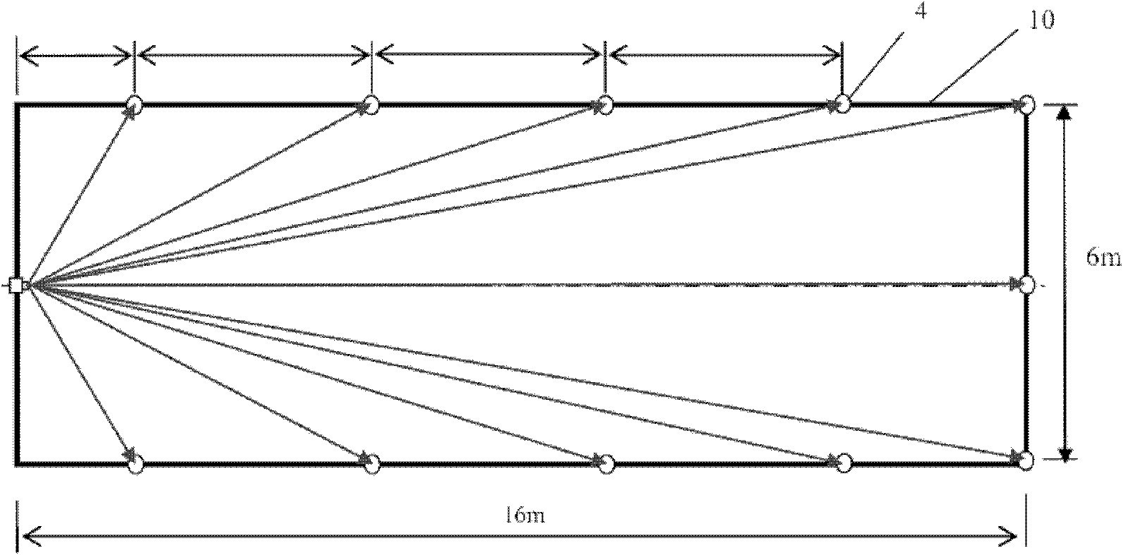
[0035] The layout of the visual inspection system is as follows figure 2 As shown, a total of 11 measurement positions are set, and a total of 11 reflective marks are arranged, which are distributed on a rectangular frame with a length of 16m and a width of 6m. The vertical deformation displacement of each mark is ±50mm.

[0036] The camera 2 is a high-precision industrial area array CCD camera with a pixel of 2035×1684pixel. The lens 3 is designed and selected according to the size, distance and moving range of the measured obje...


PUM

PropertyMeasurementUnit
Diameteraaaaaaaaaa

Abstract

The invention discloses a vision detection system and method capable of resisting sunlight interference, belonging to the technical field of vision detection. The system comprises a camera, laser, a reflective marker and a processing system, wherein the laser and the camera are arranged at a measuring point of the detection system in parallel and are respectively connected with the processing system; the reflective marker is arranged at any characteristic point of a target to be measured and has no mutual displacement with the target to be measured; the laser is connected with the processing system and is used for receiving a control command; the laser is used for radiating laser rightly opposite to the reflective marker and illuminating the reflective marker; the camera is used for acquiring an image of the reflective marker and transmitting the image to the processing system; and the processing system is used for processing the image and acquiring the specific position of the reflective marker. According to the vision detection system and method disclosed by the invention, semiconductor laser beams are adopted to directionally illuminate; the reflective marker is produced by using a film material with retroreflectivity and is used for directionally reflecting incident light of an active light source; the influence from sunlight is effectively reduced by using narrow-band light filtering; and the stability and the detection precision of the detection system are remarkably improved.

Description

technical field [0001] The present invention relates to a system and method in the technical field of visual inspection, in particular to a visual inspection system and method capable of resisting sunlight interference. Background technique [0002] The visual inspection system uses theories and methods of computer technology, digital image processing technology, image matching pattern recognition, photogrammetry and other disciplines to complete the measurement of objects, so it has excellent performance such as high intelligence, high detection efficiency, and high measurement accuracy. be widely used. A more common situation in actual measurement is to use several feature points of the measured object (such as setting some special signs) to obtain relevant information. Therefore, the accuracy of the entire measurement system depends on the accuracy of positioning the center of the mark, and the reliability of the entire detection system depends on whether a clear image o...

Claims


Application Information

Patent Timeline
IPC IPC(8): G01C11/02G01C11/04G01C15/00
Inventor 赵辉陶卫刘伟文刘炜浩杨金峰
Owner 上海砺晟光电技术有限公司
Learn More