Power sensor frequency characteristic test compensation device and method thereof

A technology of frequency characteristics testing and power sensors, applied in the direction of measuring devices, single semiconductor device testing, instruments, etc., can solve the problem of the method and device for detecting frequency characteristics without test diodes, and the compensation network cannot be designed into a uniform parameter circuit, which is difficult to meet Product production and debugging needs and other issues to achieve the effect of saving manpower, reducing the difficulty of debugging, and shortening the delivery cycle

Active Publication Date: 2011-11-30
BEIJING BBEF SCI & TECH
View PDF4 Cites 3 Cited by
  • Summary
  • Abstract
  • Description
  • Claims
  • Application Information

AI Technical Summary

Problems solved by technology

Due to the inconsistency of the detection frequency characteristics of diodes, this kind of compensation network cannot be designed as a circuit with uniform parameters. It can only be prepared by power-on and debugging, and it needs to be debugged and measured one by one, including replacing resistors, capacitors, and even detection. diode
It is conceivable that the debugging time is long and the power consumption is large, and rich debugging experience is required
However, the existing diode standards do not have indicators related to the detection frequency characteristics, and there is no method and device for testing the detection frequency characteristics of diodes.
[0004] As high-power transmitters have higher and higher requirements for power sensor detection accuracy and DC detection frequency characteristics, the existing design and debugging technology has been difficult to meet the needs of product production and debugging

Method used


Image

  • Power sensor frequency characteristic test compensation device and method thereof
  • Power sensor frequency characteristic test compensation device and method thereof
  • Power sensor frequency characteristic test compensation device and method thereof

Examples


Embodiment Construction

[0036] The aforementioned and other technical contents, features and effects of the present invention will be clearly presented in the following detailed description of preferred embodiments with reference to the drawings. Through the description of the specific implementation mode, when the technical means and functions adopted by the present invention to achieve the predetermined purpose can be obtained a deeper and more specific understanding, but the accompanying drawings are only for reference and description, and are not used to explain the present invention be restricted.

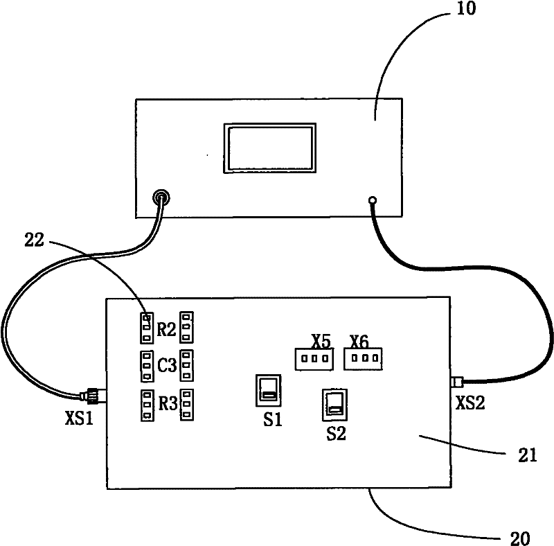
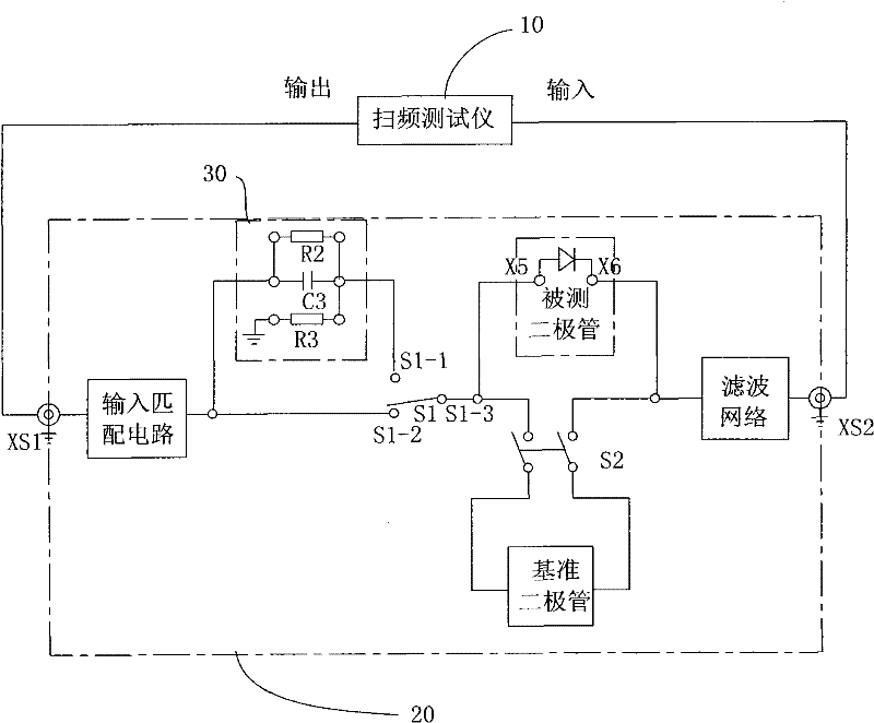
[0037] see figure 2 , image 3 As shown, a power sensor frequency characteristic test compensation device provided by the present invention includes a frequency characteristic tester 10 for testing and a power sensor test compensation small box 20, wherein the panel 21 of the test compensation small box 20 is provided with There are resistance and capacitor jacks 22 of the debugging compensation n...


PUM


Abstract

The invention relates to a device and a method for testing and compensating, in particular to a device and a method for testing and compensating frequency characteristics of a power sensor. The device comprises a frequency characteristic tester and a power sensor testing and compensating small box. Resistance and capacitance jacks of a debugging and compensating network and diode jacks X5 and X6 are arranged on a panel of the testing and compensating small box. A radio frequency connector is arranged on the small box near the side surfaces of the jacks of the debugging and compensating network. The radio frequency connector is connected with a high-frequency signal output end of the frequency characteristic tester. A direct current output connector is arranged on a side surface near the diode jacks. The direct current output connector is connected with an input end of a frequency characteristic tester. An input end of the debugging and compensating network is connected with the radio frequency connector. An output end of the debugging and compensating network is connected with the diode jack X5. The diode jack X6 is connected with the direct current output connector. According to the device and the method disclosed by the invention, a high-efficiency solution for designing and debugging the power sensor is provided; the debugging problem is reduced; and properties of products are improved.

Description

technical field [0001] The invention relates to a test compensation device and a method thereof, in particular to a power sensor frequency characteristic test compensation device and a method thereof for a high-power transmitter. Background technique [0002] The detection of the output power of a high-power transmitter is very important to the normal operation and protection of the transmitter. Usually, a directional coupler or a voltage divider is connected to the output of the transmitter to take out a suitable high-frequency output signal, which is converted into a DC voltage signal by a detection diode after a compensation network, and then sent to an indicating circuit or a microprocessor for processing. Before entering practical use, the detection diode and its compensation circuit must be debugged and calibrated for indication accuracy and frequency response. This usually needs to be done on the whole machine. First connect the transmitter to a dummy load of corres...

Claims


Application Information

Patent Timeline
IPC IPC(8): G01R31/00G01R31/26G01R23/00
Inventor 刘应阶李清亮郝书吉闫玉波王全友杨丽华曹海鹏
Owner BEIJING BBEF SCI & TECH
Why Eureka
Try Eureka