
Power plant with co2 capture

A technology of power equipment and gas turbines, which is applied in the direction of mechanical equipment, machines/engines, steam engine devices, etc., and can solve problems such as performance, efficiency, and operability.

Inactive Publication Date: 2011-11-30
ALSTOM TECH LTD
View PDF1 Cites 4 Cited by
  • Summary
  • Abstract
  • Description
  • Claims
  • Application Information

AI Technical Summary

Problems solved by technology

CO 2 This change in concentration for CO 2 potentially detrimental to the performance, efficiency, and operability of capture systems

Method used


Image

  • Power plant with co2 capture
  • Power plant with co2 capture
  • Power plant with co2 capture

Examples


Embodiment Construction

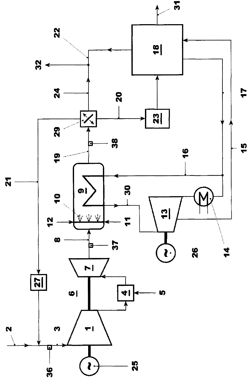
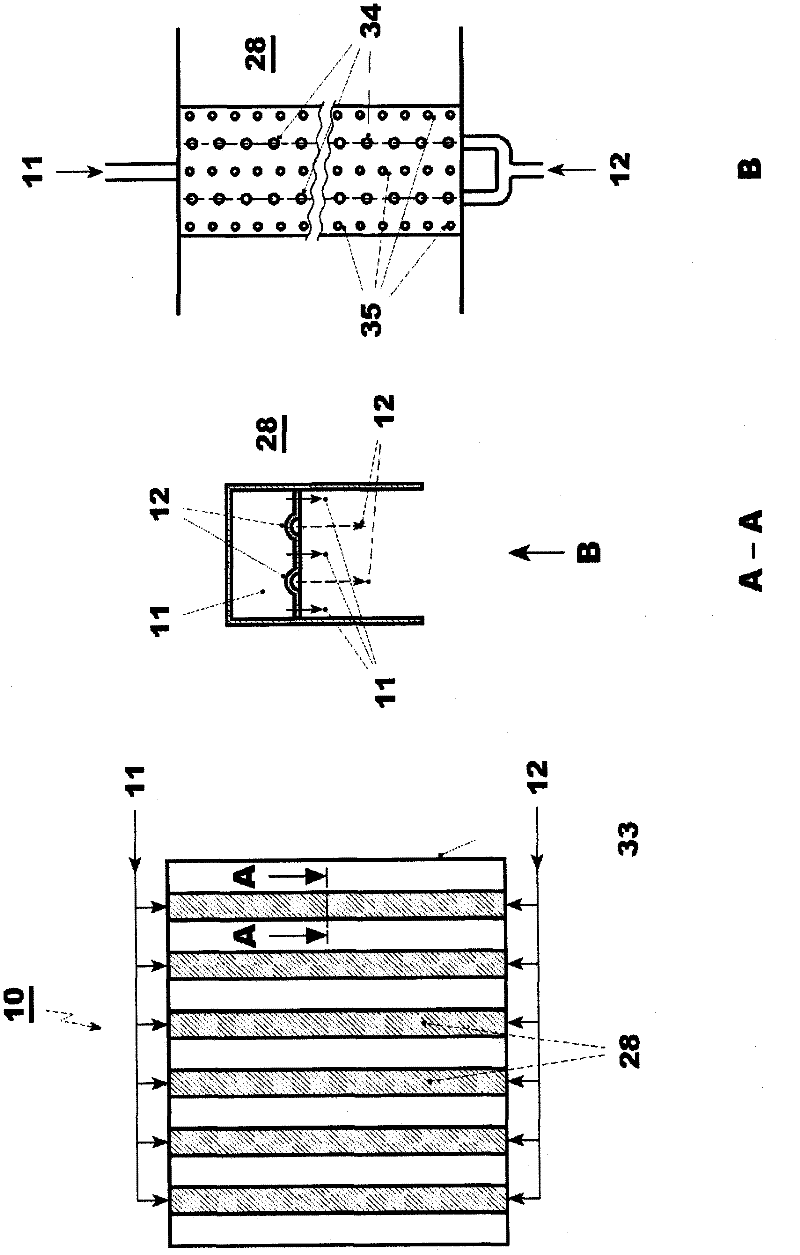
[0044] The power plant used to perform the proposed method includes a conventional CCPP, equipment for flue gas recirculation, afterburner 10, and CO 2 capture system 18 .

[0045] exist figure 1 A typical arrangement with post combustion capture, flue gas recirculation and afterburner 10 is shown in . Compressor inlet gas 3 and fuel 5 are supplied to a gas turbine 6 that drives a first generator 25 . The compressor inlet gas 3 is a mixture of ambient air 2 and a first partial stream 21 of flue gas which is recirculated through the flue gas recirculation line. Inlet gas is compressed in compressor 1 . The compressed gas is used in combustor 4 to burn fuel 5 and the pressurized hot gas is expanded in turbine 7 . Its main outputs are electrical power and hot flue gas8.

[0046] The hot flue gas 8 of the gas turbine passes through the HRSG 9 which produces steam 30 for the steam turbine 13 . An afterburner 10 is integrated in the HRSG 9 or in the flue gas duct from the gas ...


PUM


Abstract

Since CO2 is identified as a main greenhouse gas, its capture and storage is essential to control global warming. Flexible operation of CCPPs (combined cycle power plants) with CO2 capture system (18) will increase the competitiveness of CCPPs designed for CO2 capture and will allow earlier introduction of this kind of plants. The main objective of the present invention is to increase the CCPP net power and improve the operating characteristics by taking advantage of the additional power and flexibility, which can be obtained with supplementary firing (10) in CCPPs with flue gas recirculation and CO2 capture systems (18). One particular aim is to minimize the impact of CO2 capture on the capacity of a power plant, i.e. to maximize the electric power the plant can deliver to the power grid.; To this end an operating method, in which the power consumption of CO2 capture system is at least partly compensated by the operation of supplementary firing (10) in a HRSG (9) with low residual oxygen concentration in the flue gases (8), which is due to flue gas recirculation, is proposed. Further, additional ambient air and / or oxygen (11 ) injection into the supplementary firing (10) with corresponding operating methods are proposed. Besides the method a CCPP designed to operate according to this method is subject of the present invention.

Description

technical field [0001] The present invention relates to an integrated CO 2 Capture and afterburner combined cycle power plants and their operation. Background technique [0002] In recent years, it has become apparent that the production of greenhouse gases leads to global warming and that further increases in the production of greenhouse gases will accelerate global warming. Because CO 2 (Carbon dioxide) is recognized as a major greenhouse gas, so CCS (Carbon Capture and Storage) is seen as one of the potential major means to reduce the release of greenhouse gases into the atmosphere and control global warming. In this context, CCS is defined as CO 2 The process of capturing, compressing, transporting and storing. Capture is defined as a process in which CO 2 Either from the flue gas after combustion of the carbon-based fuel, or by removing and treating the carbon prior to combustion. Any absorbent, sorbent or used to remove CO from flue gas or fuel gas streams 2 The...

Claims


Application Information

Patent Timeline
IPC IPC(8): F01K23/10
CPCY02E20/16F01K23/105Y02E20/32Y02E20/34F02C6/18
Inventor 李洪涛H·纳格尔T·努格罗霍C·马耶
Owner ALSTOM TECH LTD
Learn More