Assembly mold and assembly method for car fuel filler cap hinge

A fuel filler cap and hinge technology, which is applied in the field of mold structure and technology, can solve the problems of difficulty in taking out the card mold, cannot be used directly, and difficult to assemble the shaft, and achieves the effect of eliminating batch quality problems, facilitating mold maintenance and fewer processes.

Active Publication Date: 2011-12-07
LIAN WEI AUTO PARTS CHONQGING
View PDF5 Cites 9 Cited by
  • Summary
  • Abstract
  • Description
  • Claims
  • Application Information

AI Technical Summary

Problems solved by technology

[0010] 1) Part of the incoming head of the shaft raw material is seriously deformed and cannot be used directly. It is necessary to cut off the deformed part with a shearing machine before it can be used normally;
[0011] 2) When the shaft and the hinge are matched, there are requirements for the degree of tightness after assembly, so the hinge must be molded in place at one time, and then manually assembled, resulting in difficulty in shaft assembly;
[0013] 4) After the shaft is flattened, the size becomes longer, and the mold is stuck, which makes it difficult to pick up the parts

Method used


Image

  • Assembly mold and assembly method for car fuel filler cap hinge
  • Assembly mold and assembly method for car fuel filler cap hinge
  • Assembly mold and assembly method for car fuel filler cap hinge

Examples


Embodiment Construction

[0049] The structure of the present invention is described in detail below in conjunction with accompanying drawing:

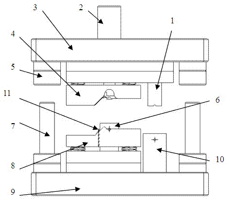
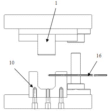
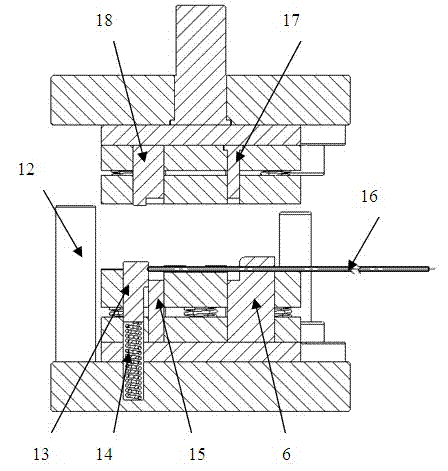
[0050] see Figure 1 to Figure 4 , the mold consists of an upper die 3, a lower die 9, a head cutting punch 1, a head cutting die 10, an upper shaping binder plate 4, a lower shaping pressing plate 8, a cutting and flattening punch 17, a cutting and flattening die 6. It is composed of flattening punch 18, flattening die 15, movable positioning mechanism, die handle 2, guide post 7, guide sleeve 5, limit post 12 and positioning pin 11, etc.

[0051] Die handle 2 is fixed on the upper die, plays the effect of installing the upper die, and is directly connected with the slide block of the machine tool.

[0052] Head cutting punch 1, cutting and flattening punch 17 and flattening punch 18 are fixed on the upper die side by side, head cutting die 10, cutting and flattening die 6 and flattening die 18 are correspondingly fixed on the lower die side by side, This p...


PUM


Abstract

The invention relates to an assembling mould for a car oil filler cap hinge, and the assembling mould provided by the invention comprises an upper mould, a lower mould, a crop convex mould, a crop concave mould, an upper reshaping pressing plate, a lower reshaping pressing plate, a cutting beating convex mould, a cutting beating concave mould, a beating convex mould, a beating concave mould, a moveable positioning mechanism, a positioning pin, and the like. A plurality of processes, such as shaft cutting, shaft baiting, hinge and shaft assembling, shaft beating, hinge forming, and the like, are simultaneously finished on one mould, thereby achieving the purposes of low cost, high efficiency and low energy consumption.

Description

technical field [0001] The invention relates to a mold structure and technology. Background technique [0002] In order to reduce energy consumption, save costs, and improve efficiency, the current production process of auto parts is developing in the direction of low cost, high efficiency, and low energy consumption. In view of this, how to reduce the process, cancel or reduce manual work, and use mold making as much as possible in the process design of automobile stamping parts has become one of the key points considered by the auto parts manufacturing industry. The mechanical automation production of auto parts manufacturing has become the The trend of industry development. [0003] According to the applicant's research on the hinge assembly process of the car fuel filler cap, it is found that the traditional process has many processes, low efficiency, and high cost. The process content is as follows: [0004] 1) Shaft cutting head: the head is cut by a shearing machine...

Claims


Application Information

Patent Timeline
Patent Type & Authority Applications(China)
IPC IPC(8): B21D37/10
Inventor 罗旭牟燕张健刘佳
Owner LIAN WEI AUTO PARTS CHONQGING
Why Eureka
Try Eureka