Supercharge Your Innovation With Domain-Expert AI Agents!

A combined process and device for C4 hydrocarbon catalytic cracking and heavy oil catalytic cracking

A catalytic cracking and heavy oil catalytic technology, which is applied in the petroleum industry, hydrocarbon oil treatment, multi-stage parallel refining and cracking process treatment, etc., can solve the problems of low ethylene-propylene selectivity, increased equipment investment, and large floor area , to achieve the effect of high regeneration efficiency, small footprint and low investment

Inactive Publication Date: 2011-12-07
CHINA PETROCHEMICAL CORP +1
View PDF3 Cites 10 Cited by
  • Summary
  • Abstract
  • Description
  • Claims
  • Application Information

AI Technical Summary

Problems solved by technology

[0008] CN1624078A discloses a dual-catalyst system coupling regeneration process method, using high-temperature catalytic cracking regenerated catalyst in the secondary regenerator to heat and regenerate the special catalyst of the new process; CN1626623A discloses a dual-reaction regeneration system multi-effect coupling flow Catalytic reaction process method, the high-temperature flue gas of the catalytic cracking regenerator is introduced into the sub-regenerator to heat the special catalyst of the new process and make it regenerated; but both CN1624078A and CN1626623A technologies need to set up a sub-regenerator for the regeneration of the special catalyst, resulting in Increased investment in equipment and a large footprint
CN1935349A discloses a gas-solid fluidization coupling device and a coupling method using the device for multi-stage mixing, heat exchange, reaction and classification of large difference particles, but the device is relatively complicated
USP7491315 discloses a double riser reactor C 4 Cracking and heavy oil cracking process, but USP7491315 technology due to C 4 The same catalyst is used for cracking and heavy oil cracking, and the selectivity of ethylene and propylene is low

Method used


Image

  • A combined process and device for C4 hydrocarbon catalytic cracking and heavy oil catalytic cracking
  • A combined process and device for C4 hydrocarbon catalytic cracking and heavy oil catalytic cracking

Examples


Embodiment Construction

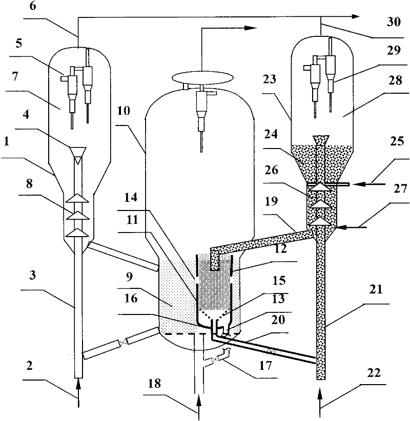
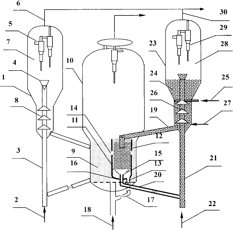
[0026] As shown in the figure, the heavy feed oil 2 containing atomized steam enters the riser reactor 3 of the heavy oil catalytic cracking unit 1 from the bottom, and reacts with the high-temperature catalytic cracking regenerated catalyst from the main regenerator 10 at a reaction temperature of 460-560°C. , the heavy feed oil preheating temperature is 150-300°C, the catalyst-to-oil ratio (the weight ratio of the catalytic cracking catalyst in the riser reactor 3 to the heavy feed oil) is 2-10, the catalyst activity is 50-70, and the reaction time is 1.0-6.0s, contact, gasification, mixing and reaction under the condition of reaction pressure of 0.1-0.4MPa, oil gas, water vapor and catalyst pass through the riser reactor 3, and then enter the gas-solid separation device 4 and the main settler The main cyclone separator 5 of 7 is separated, and the separated main reaction oil gas 6 enters the fractionation system, and the separated catalyst to be born enters the main settler ...


PUM

PropertyMeasurementUnit
particle diameteraaaaaaaaaa

Abstract

The invention discloses a combined process and device for catalytic cracking of C4 hydrocarbons and catalytic cracking of heavy oil. Its main technical features are: combining C4 hydrocarbon catalytic cracking and heavy oil catalytic cracking reaction regeneration processes together, a sub-regenerator is set in the dense phase section of the main regenerator, and the standby catalyst for C4 hydrocarbon catalytic cracking enters the sub-regenerator, and enters the The high-temperature catalytic cracking semi-regenerated catalyst in the secondary regenerator is mixed and then regenerated. Most of the regenerated catalytic cracking catalyst returns to the main regenerator. The regenerated C4 cracking catalyst and a small amount of catalytic cracking catalyst enter the C4 hydrocarbon catalytic cracking reactor for recycling. Using the invention, the excess heat of the heavy oil catalytic cracking unit can be used for the catalytic cracking reaction process of C4 hydrocarbons with insufficient heat to increase the production of ethylene propylene.

Description

technical field [0001] The invention belongs to the field of catalytic conversion of petroleum hydrocarbons, in particular, relates to heavy oil catalytic cracking process and C 4 The combined process technology of the catalytic cracking process of hydrocarbons, in particular, relates to a high-efficiency combined fluidized catalytic reaction process and device of a double-reaction double-catalyst regeneration system. Background technique [0002] Propylene is one of the important petrochemical basic raw materials. In recent years, the demand for propylene has been increasing worldwide. The sources of propylene mainly include: by-products of steam cracking in ethylene plants (accounting for about 68%), by-products of catalytic cracking (accounting for about 29%), propane dehydrogenation, etc. ( 3%). The main raw material of steam cracking is naphtha, and there is a shortage of raw materials; while the conventional yield of propylene by-product of fluid catalytic cracking u...

Claims


Application Information

Patent Timeline
Patent Type & Authority Applications(China)
IPC IPC(8): C10G55/00C10G55/08
Inventor 常剑孟凡东王龙延闫鸿飞王文柯陈曼桥张亚西武立宪陈章淼樊麦跃
Owner CHINA PETROCHEMICAL CORP
Features
  • R&D
  • Intellectual Property
  • Life Sciences
  • Materials
  • Tech Scout
  • Unparalleled Data Quality
  • Higher Quality Content
  • 60% Fewer Hallucinations
Learn More