A temperature and humidity adjustment device for a rescue cabin

A technology of temperature and humidity regulation and life-saving cabin, which is used in safety devices, ventilation of mines/tunnels, mining equipment, etc. It can solve the problems of low reliability, affecting rescue operations, and danger, and achieve the effect of reducing consumption.

Inactive Publication Date: 2011-12-07
JIANGSU UNIV OF SCI & TECH
View PDF5 Cites 7 Cited by
  • Summary
  • Abstract
  • Description
  • Claims
  • Application Information

AI Technical Summary

Problems solved by technology

Most of the temperature and humidity adjustment devices of the existing mine rescue cabins use ice making / storage cooling or use CO 2 Refrigeration uses the ice making / storage method to realize emergency cooling, that is, the ice maker is usually used to take a certain amount of ice and store it. When a mine accident occurs, the melting and absorption heat of the ice is used to cool the air to cool down. Due to the structure of the ice storage The heat transfer will cause the ice to melt in the non-emergency period, so it is necessary to regularly check the amount of ice stored inside the storage box, and release the internal moisture to replace the ice. This will make the cumulative power consumption of ice making larger, and the system volume Huge, complex operation, low reliability; using CO 2 Refrigeration, whether utilizing solid, liquid, or compressed CO 2 Gas is used to achieve refrigeration, and the exhaust gas will eventually be discharged into the outside of the cabin, which will inevitably make the CO near the cabin 2 The gas concentration rises, causing inconvenience and even danger to rescuers and affecting rescue operations

Method used


Image

  • A temperature and humidity adjustment device for a rescue cabin
  • A temperature and humidity adjustment device for a rescue cabin

Examples


Embodiment Construction

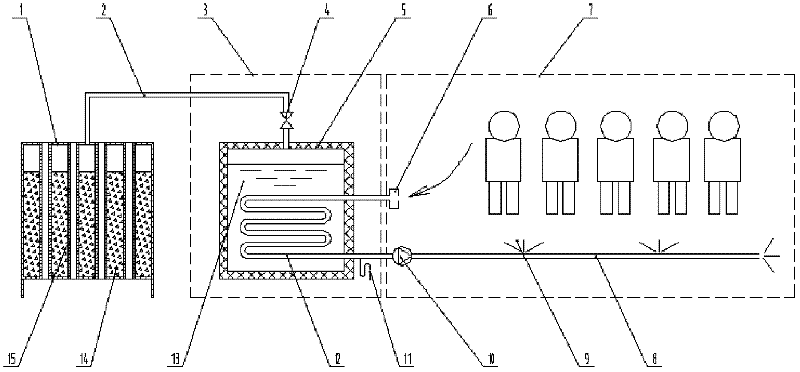
[0023] A kind of temperature and humidity adjustment device for rescue cabin of the present invention is described below in conjunction with accompanying drawing, with respect to a soft rescue cabin of 15 people, continuous lifesaving time is 96 hours, and the interior design temperature of rescue cabin 7 is 35 ℃, humidity 85%, and rescue cabin 7 The external temperature of 40°C is an example and will be further described in detail.

[0024] A temperature and humidity adjustment device for a rescue cabin according to the present invention includes an absorber 1, a steam pipeline 2, an equipment cabin 3, a stop valve 4, an evaporator 5, an air return port 6, a rescue cabin 7, and an air supply pipe 8 , air outlet 9, air pump 10, condensate pipe 11, surface cooler 12, refrigerant 13, absorbent 14, cooling pipe 15. The absorber 1 adopts a 5mm thick plastic plate welded into a square box structure, and the upper top plate and the lower bottom plate above the ground are respectivel...


PUM


Abstract

The invention discloses a temperature and humidity regulating device for an escape capsule. The temperature and humidity regulating device comprises an absorber, an evaporator arranged in an equipment compartment, and an air supply and return system arranged in the escape capsule, wherein a plurality of upper and lower coaxial through holes are formed on the upper top plate and the lower bottom plate of the absorber; a cooling pipe is arranged in the corresponding upper and lower through holes vertically; a closed chamber is formed between the cooling pipe and the shell of the absorber; a surface cooler is arranged on the wall of the evaporator; the inlet end and the outlet end of the surface cooler pass through the side wall of the equipment compartment, respectively; the inlet end is communicated with an air return inlet in the escape capsule, and the outlet end is communicated with an air supply pipe which is equipped with an air pump and an air supply outlet in sequence and is disposed in the escape capsule; a water condensing pipe is arranged at the outlet end of the surface cooler; a hole, which is communicated with one end of a steam pipeline, is formed on the upper top plate of the absorber corresponding to the chamber; the other end of the steam pipeline, on which a stop valve is arranged, is communicated with the top end of the evaporator. The temperature and humidity regulating device disclosed by the invention is free from repeated filling of cool storage materials, free of energy consumption, small in volume, simple in structure and convenient in operation.

Description

technical field [0001] The invention relates to the technical field of refrigeration, in particular to a non-powered temperature and humidity adjustment device for a mine rescue cabin. Background technique [0002] The mine rescue cabin is a sealing device used by the operators to take refuge and wait for rescue when a disaster or accident occurs underground in the mine. The construction standard of the mine rescue cabin requires that it should have the function of temperature and humidity adjustment, the temperature is ≤35°C, the humidity is 85%, and the protection duration is not less than 96 hours. In addition, environmental parameter monitoring instruments must be equipped to detect harmful gases inside and outside the rescue chamber. The concentration of these harmful gases must not exceed the relevant safety standards. Because when an accident occurs, the power system under the mine may be destroyed, so any equipment in the rescue cabin requires that it can work norma...

Claims


Application Information

Patent Timeline
Patent Type & Authority Applications(China)
IPC IPC(8): E21F3/00E21F11/00
Inventor 周根明唐春丽赵忠超郭霆
Owner JIANGSU UNIV OF SCI & TECH
Why Eureka
Try Eureka