Slideway blade system for vertical wind turbines

A wind power generator and slideway technology, applied to wind power generators, wind power generators at right angles to the wind direction, engines, etc., can solve the problem of large start-up dead angle and reversing dead angle, small wind-receiving area of ​​airfoil blades, and wind utilization Low efficiency and other issues, to achieve the effect of good balance characteristics, high wind utilization rate, increased stability and safety

Inactive Publication Date: 2011-12-07
李树广 +1
View PDF6 Cites 3 Cited by
  • Summary
  • Abstract
  • Description
  • Claims
  • Application Information

AI Technical Summary

Problems solved by technology

[0005] The purpose of the present invention is to solve the problem that the blades of the existing vertical wind power generators have a large starting dead angle and a large commutation dead angle during starting and rotating motion, and the airfoil blades have a small wind receiving area and a low wind utilization rate. There is a wind resistance surface on the front airfoil, and it is difficult to increase the capacity, and then provide a slide-type fan blade system for vertical wind turbines

Method used


Image

  • Slideway blade system for vertical wind turbines
  • Slideway blade system for vertical wind turbines
  • Slideway blade system for vertical wind turbines

Examples


specific Embodiment approach 1

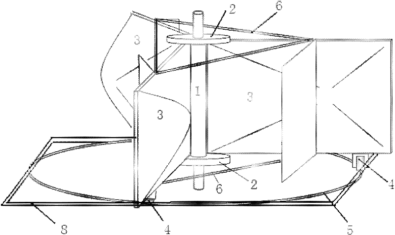
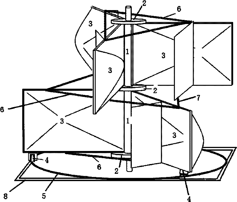
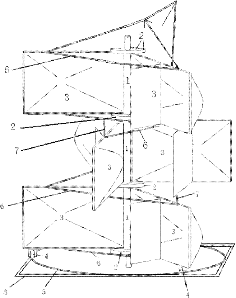
[0022] Specific implementation mode one: combine figure 1 and Figure 4 To illustrate this embodiment, the slideway-type fan blade system of the vertical wind power generator in this embodiment is a single-layer fan blade system, and the single-layer fan blade system includes a compound shaft 1, two shaft fan blade connection methods Blue plate 2, three single fan blades 3, three fan blade pulleys 4, fan blade annular slideway 5 and two triangular fan blade fixing frames 6, the two machine shaft fan blades are connected to the flange 2 installed on On the composite machine shaft 1, three single fan blades 3 are connected between the connecting flanges 2 of the two machine shaft fan blades, and the three single fan blades 3 surround the composite machine shaft 1 in a ring, The three single blades 3 are arranged at an angle of 120 degrees, the upper ends of the three single blades 3 are fixedly connected by a triangular blade fixing frame 6, and the lower ends of the three sing...

specific Embodiment approach 2

[0023] Specific implementation mode two: combination figure 1 , Figure 4 to Figure 6Describe this embodiment, the single fan blade 3 of this embodiment includes a refraction wind deflector 3-2, a fan blade frame 3-3, a fan blade body 3-4, two support frames 3-5 and two fan blades Shaft fixing part 3-1, fan blade body 3-4 is composed of shell and internal skeleton welded as a whole, the outer contour line of the outer shell cross section of fan blade body 3-4 is a convex arched curve, and the fan blade body The outer contour of the longitudinal section of the shell of 3-4 is a wing streamline curve, the fan blade frame 3-3 is welded on the plane of the fan blade body 3-4, and the fan blade frame 3-3 and the compound shaft 1 are close to one end A fan shaft fixing part 3-1 is installed on the upper and lower sides of the upper and lower sides respectively, and the single fan blade 3 establishes a mechanical connection with the shaft fan connecting flange 2 through the fan shaf...

specific Embodiment approach 3

[0024] Specific implementation mode three: combination Figure 4 To illustrate this embodiment, the internal skeleton of the fan blade body 3-4 in this embodiment is a steel belt mesh skeleton or a steel wire mesh skeleton, and the outer shell of the fan blade body 3-4 is made of glass fiber reinforced plastic or carbon fiber. With such setting, the surface is smooth and the wind resistance is small. Other compositions and connections are the same as those in the second embodiment.


PUM


Abstract

The utility model relates to a slideway type wind blade system of a vertical wind power generator, which relates to a wind blade system of a vertical wind power generator. The present invention aims to solve the problem of large starting dead angle and large reversing dead angle in the starting and rotating motion of the existing fan blade, and the problem that the airfoil fan blade has a small wind-receiving area and is difficult to increase the capacity. Scheme 1 is a single-layer fan blade system. There are three single fan blades connected between the connecting flanges of the two shaft fan blades. The three single fan blades are ring-shaped around the compound shaft. The body blades are arranged at an angle of 120 degrees. The upper and lower ends of the three single blades are fixedly connected by a triangular blade fixing frame, and a blade pulley is installed at the lower end of each single blade. The blade annular slideway is fixedly installed on the frame beam, and the fan blade pulley slides on the slideway. The difference between Scheme 2 and Scheme 1 is that it is a double-layer fan blade system. The difference between Scheme 3 and Scheme 1 is that it is a multi-layer fan blade system. The invention is used in wind power generation.

Description

technical field [0001] The invention relates to a wind blade system of a vertical wind power generator, in particular to a slideway type wind blade system of a vertical wind power generator, which belongs to the technical field of wind power generation. Background technique [0002] With the development of the world's energy crisis, the use of wind kinetic energy as a new energy source for the development of modern society has become a hot spot in social development. The traditional three-blade wind turbine has no wind collection and protection system, the utilization rate of wind power is low, the volume of the wind turbine is large, and the long blades are difficult to transport, install and maintain, and are easily damaged. The blades of the existing vertical wind turbines have the problem of large start-up dead angle and large reversing dead angle during startup and rotation. , There is a commutation dead angle in the rotary motion, and it is difficult to increase the c...

Claims


Application Information

Patent Timeline
Patent Type & Authority Applications(China)
IPC IPC(8): F03D3/06F03D3/02
CPCY02E10/74
Inventor 李树广
Owner 李树广
Why Eureka
Try Eureka