A method for reducing the pressure of pump sealing chamber

A sealing cavity and pressure technology, which is applied to components, pumps, and pump components of elastic fluid pumping devices, can solve the problem of high pressure in the sealing cavity, and achieve the effects of reducing investment, reducing pressure, and reducing pressure

Active Publication Date: 2011-12-07
CHINA PETROCHEMICAL CORP +1
View PDF8 Cites 4 Cited by
  • Summary
  • Abstract
  • Description
  • Claims
  • Application Information

AI Technical Summary

Problems solved by technology

[0013] The invention provides a method for reducing the pressure of the sealing chamber of the pump, which solves the problem of high pressure in the sealing chamber of the pump inlet and outlet of the prior art.

Method used


Image

  • A method for reducing the pressure of pump sealing chamber
  • A method for reducing the pressure of pump sealing chamber
  • A method for reducing the pressure of pump sealing chamber

Examples


Embodiment Construction

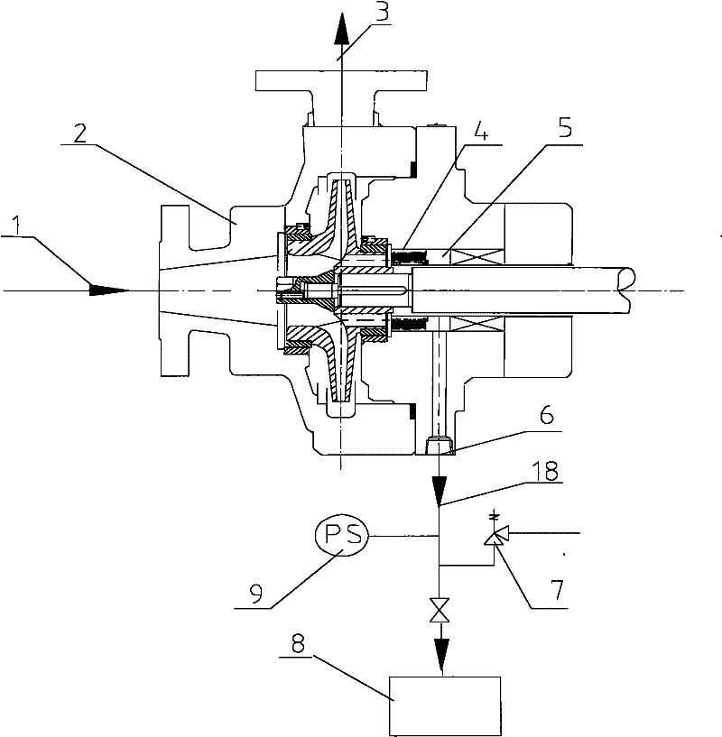
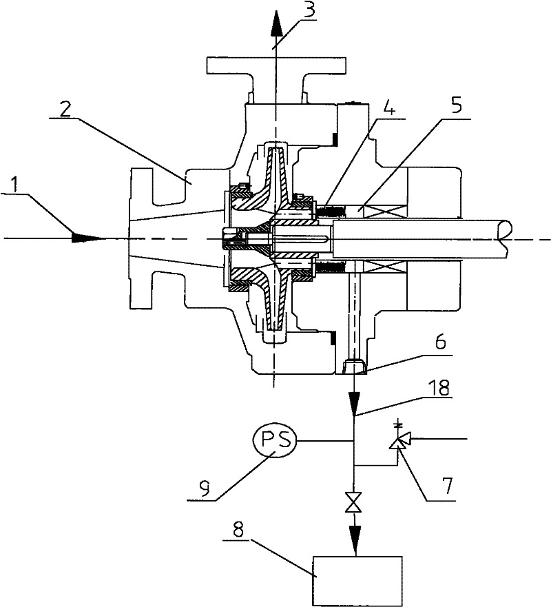
[0037] Such as figure 1 As shown, the high-pressure fluid 1 with a pressure of 4.0-35.0MPa enters the pump body 2, and is discharged from the pump body 2 after pressurization, becoming a high-pressure flow 3, and the liquid discharged from the balance drum or throttling bush 4 arranged in front of the sealing chamber 18 leads to the pressure of 0.1 ~ 4.0MPa low-pressure container 8 through the liquid outlet 6.

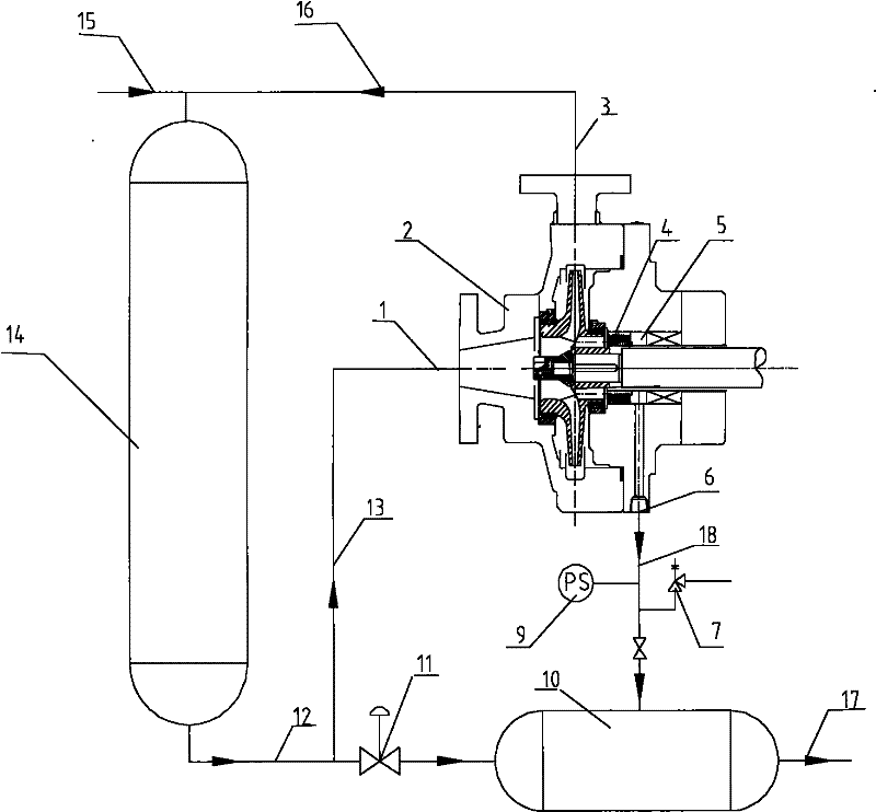
[0038] figure 2 As shown, part of the reaction effluent 13 from the high-pressure hydrogenation reactor with a pressure of 7.0-20.0 MPa enters the pump body 2, and is discharged from the pump body 2 after being pressurized to become a high-pressure stream 16. The high-pressure stream 16 is combined with the new hydrogenation raw material 15 mixed into the high-pressure reactor 14 for hydrogenation reaction, the liquid 18 discharged from the balance drum or throttling bushing 4 arranged in front of the sealed cavity is led to a pressure of

[0039] A safety relief va...


PUM


Abstract

The invention discloses a method for reducing the pressure of a pump sealing cavity, which is characterized in that it comprises the following steps: 1) high-pressure fluid enters the pump body from the inlet of the pump, and is discharged from the pump body after being pressurized by the pump; The liquid discharged from the balance drum or throttling bush is led to the low-pressure container outside the pump body. The invention overcomes the problem that the prior art pump inlet and outlet are both high-pressure sealing chambers with high pressure and difficulty in sealing.

Description

technical field [0001] The invention relates to the field of pumping liquid with a rotary pump, relates to a pump for lifting fluid through centrifugal force, and in particular to a method for reducing the pressure of a sealing cavity of a high-pressure circulating oil pump. technical background [0002] The centrifugal pump is designed according to the principle of centrifugal force. The high-speed rotating impeller blades drive the fluid to rotate, and the fluid is thrown out, so as to achieve the purpose of transportation. High-pressure pumps are mainly used as process pumps in petroleum, chemical and fertilizer industries. [0003] Ordinary high-pressure pump seals generally have a lower inlet pressure and a higher outlet pressure of the pump. In order to facilitate the sealing of the seal chamber, the two sides of the impeller of the pump are balanced through the balance hole or the auxiliary impeller to balance the axial force, and then through the Throat bushing is u...

Claims


Application Information

Patent Timeline
Patent Type & Authority Applications(China)
IPC IPC(8): F04D29/08F04D7/06
Inventor 杨成炯朱华兴
Owner CHINA PETROCHEMICAL CORP
Why Eureka
Try Eureka