Pipeline conveying line and conveying method

A technology for conveying lines and pipe bodies, which is applied in the field of conveying lines, can solve the problems of high investment cost, increased site occupation area, and large site occupied area of ​​linear assembly lines, so as to save the occupied area of ​​the site, reduce the occupied area of ​​the site, and save effect of space

Active Publication Date: 2020-01-03
远大可建科技有限公司
View PDF5 Cites 0 Cited by
  • Summary
  • Abstract
  • Description
  • Claims
  • Application Information

AI Technical Summary

Problems solved by technology

[0002] The existing pipe body conveying line usually sets a long straight line on the ground from pipe making to processing pipe body to application of pipe body, for example, the pipe body output from the pipe making / pipe cutting device passes through the straight line Enter the pipe body processing device for reprocessing, and the processed pipe body enters the next process equipment through the linear assembly line, which greatly increases the occupied area of ​​the site, and the linear assembly line has high investment costs and low work efficiency
Moreover, in the existing pipe body conveying line, each device interferes with each other and cannot work independently, which further reduces the work efficiency
Furthermore, the existing pipe body conveying lines are all located on the ground, which makes the structure scattered and the site occupies a large area.

Method used


Image

  • Pipeline conveying line and conveying method
  • Pipeline conveying line and conveying method
  • Pipeline conveying line and conveying method

Examples


Embodiment Construction

[0029] The present invention will be further described in detail below in conjunction with the accompanying drawings and specific embodiments.

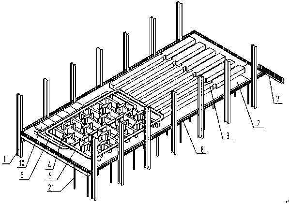
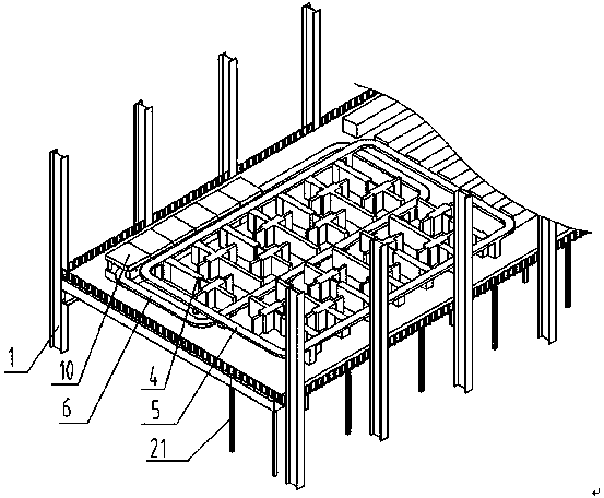
[0030] Such as figure 1 and figure 2 Shown: a pipe body conveying line, including a support frame 1 and a carrying platform 2 connected to the support frame 1. The carrying platform 2 shown is equipped with multiple pipe making / cutting devices 3 and multiple pipe body processing devices 4 , the outer ring track 5 and the inner ring track 6; the pipe making / pipe cutting device 3 is arranged on the outside of the outer ring track 5, and is used to transport the produced pipe body to the outer ring track 5; the outer ring track 5 surrounds the periphery of the pipe body processing device 4, and is used to deliver the pipe body produced by the pipe making / cutting device 3 to the pipe body processing device 4; the output end of the pipe body processing device 4 is connected to the inner The circular track 6 is opposite, and is used for ...


PUM


Abstract

The invention discloses a pipeline conveying line and conveying method. The pipeline conveying line comprises a supporting frame and a bearing platform connected with the supporting frame. Multiple pipe manufacturing / pipe cutting devices, multiple pipe body machining devices, an outer ring line rail and an inner ring line rail are arranged on the bearing platform. The pipe manufacturing / pipe cutting devices are arranged on the outer side of the outer ring line rail and are used for conveying manufactured pipe bodies to the outer ring line rail. The outer ring line rail surrounds the peripheryof the pipe body machining devices and is used for conveying the pipe bodies manufactured by the pipe manufacturing / pipe cutting devices to the pipe body machining devices. The output ends of the pipebody machining devices are opposite to the inner ring line rail, and the pipe body machining devices are used for conveying the machined pipe bodies to the inner ring line rail. The invention furthercomprises a conveying method of the pipeline conveying line. The site occupied area is greatly reduced, and cost is reduced; and equipment can operate independently and does not interfere with one another, and production efficiency is greatly improved.

Description

technical field [0001] The invention relates to a conveying line, in particular to a pipe body conveying line and a conveying method thereof. Background technique [0002] The existing pipe body conveying line usually sets a long straight line on the ground from pipe making to processing pipe body to application of pipe body, for example, the pipe body output from the pipe making / pipe cutting device passes through the straight line Enter the pipe body processing device for reprocessing, and the processed pipe body enters the next process equipment through the linear assembly line, which greatly increases the occupied area of ​​the site, and the linear assembly line has high investment costs and low work efficiency. Moreover, in the existing pipe body conveying line, each device interferes with each other and cannot work independently, which further reduces the work efficiency. Furthermore, the existing pipe body conveying lines are all arranged on the ground, so that the st...

Claims


Application Information

Patent Timeline
Patent Type & Authority Applications(China)
IPC IPC(8): B65G37/00B65G47/90B65G35/00
CPCB65G35/00B65G37/00B65G47/90B65G2201/0276
Inventor 张跃徐国新宋飞跃陈榆
Owner 远大可建科技有限公司
Why Eureka
Try Eureka