Measuring apparatus for operation behavior on pedal by driver and monitoring method thereof

A technology of drivers and pedals, which is applied in the field of automobile driver's operation behavior monitoring, can solve the problem of not being able to judge that the driver has placed his foot on a certain pedal and has not stepped on it, which affects the accuracy of the experimental results and cannot Judging and other problems to achieve the effect of intuitive detection results, convenient detection, and reduction of road traffic accidents

Active Publication Date: 2013-08-14
西安泰斯特智能测控有限责任公司
View PDF5 Cites 1 Cited by
  • Summary
  • Abstract
  • Description
  • Claims
  • Application Information

AI Technical Summary

Problems solved by technology

These two methods have certain shortcomings. The installed force sensor and displacement sensor will cause some interference to the normal operation of the driver, resulting in differences between the driver's pedal operation behavior and the normal pedal operation behavior, which affects the experimental results. accuracy of results
On the other hand, using a force sensor or a displacement sensor can only determine the pedal operation when the driver steps on the pedal, but cannot determine that the driver has placed his foot on a certain pedal and has not stepped on it. If the driver puts his foot on the brake pedal, but has not stepped on the brake pedal to brake, the driver is ready to brake
Using force sensors and displacement sensors, it is impossible to judge that the driver puts his feet on the pedals, but does not step on the pedals.

Method used


Image

  • Measuring apparatus for operation behavior on pedal by driver and monitoring method thereof

Examples


Embodiment Construction

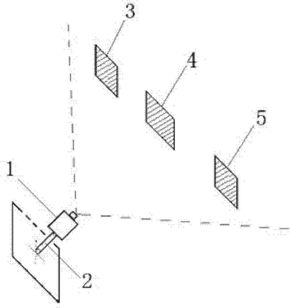
[0023] Reference figure 1 In the device for measuring the driver's pedal operation behavior, the camera is a low-light camera. In this embodiment, the camera uses a WAT-240 miniature analog camera. The low-illuminance camera 1 is fixed under the accelerator pedal, brake pedal and clutch pedal by means of a steel plate bracket 2 and is located on the floor of the cab. The lens faces the accelerator pedal 3, brake pedal 4 and clutch pedal 5. The accelerator pedal 3, the brake pedal 4, and the clutch pedal 5 are in a relatively dark environment. Therefore, the low-illuminance camera 1 can improve the brightness of the collected images.

[0024] The low-illuminance camera in this embodiment uses a WAT-240 miniature analog camera with a horizontal resolution of 480 lines. The camera is connected to a video capture card installed in the computer motherboard through a video cable, and the video capture card receives the accelerator pedal and control system. The moving images of the mov...


PUM


Abstract

The invention relates to a monitoring technology of an operation behavior of an automobile driver and discloses a measuring apparatus for an operation behavior on a pedal by a driver and a monitoring method thereof. The measuring apparatus comprises: a camera, wherein the camera is fixed on a base plate of a cab and a lens of the camera is headed to an accelerator pedal, a brake pedal, and a clutch pedal and is used for simultaneously collecting motion images of the three above-mentioned pedals; a video collection card, which is electrically connected with the camera and is used for transmitting the motion images of the three above-mentioned pedals; a computer, which is electrically connected with the video collection card and is used for receiving the motion images from the video collection card and comparing and determining actual positions of the three pedals according to foot image positions of a driver at different times to obtain a name of the pedal that is operated by the driver and operation time of the pedal, wherein the foot image positions are obtained by image processing; In addition, the monitoring method comprises the following steps: pedal position calibration; calibration on a column gray scale threshold of a pedal, image collection, image preprocessing, and determination and record on a driving behavior.

Description

Technical field [0001] The invention relates to a technology for monitoring the operation behavior of an automobile driver, in particular to a measuring device and a monitoring method for the operation behavior of a driver's pedal. technical background [0002] The driver's operation behavior on the vehicle pedal directly affects the safe operation of the vehicle and is an important part of the driving behavior. Vehicle pedals include accelerator pedal, brake pedal and clutch pedal. When conducting experimental research on driving behavior and vehicle performance, it is usually necessary to measure and record the driver’s operation behavior on the pedals. Specifically, it is necessary to measure which pedals the driver has operated at any time, the duration of operation of a certain pedal, and the The speed of switching between different pedal operations, etc., to reflect the driver's driving behavior during driving. The operation of the pedal by the driver is divided into two ...

Claims


Application Information

Patent Timeline
Patent Type & Authority Patents(China)
IPC IPC(8): G01M17/007H04N7/18
Inventor 付锐张琼马勇郭应时袁伟
Owner 西安泰斯特智能测控有限责任公司
Why Eureka
Try Eureka