Coaxial jet head for electro-hydrodynamic jet printing and application thereof

A technology of coaxial nozzles and electrofluids, which is applied in printing and other directions, can solve the problems of repeatability in the spinning process of precise positioning, the inability to realize electrospinning, and the inability to facilitate probes, so as to avoid the inability to realize continuous jet printing and promote The formation of Taylor cone, the effect of avoiding clogging

Active Publication Date: 2013-05-22
HUAZHONG UNIV OF SCI & TECH
View PDF6 Cites 2 Cited by
  • Summary
  • Abstract
  • Description
  • Claims
  • Application Information

AI Technical Summary

Problems solved by technology

[0005] At present, three types of nozzles are commonly used in the electrospinning process: the first type is a hard needle-tip nozzle with a circular cross-section, which is very prone to clogging during the electrospinning process. If a thicker nozzle is used to reduce clogging The diameter of the probe nozzle will make the diameter of the obtained fiber too thick; the second is a solid metal probe nozzle. During the electrospinning process, the probe tip is immersed in the polymer solution, and the ink is dipped in the form of a pen tip. Dip the polymer solution for direct writing of nanofibers. This nozzle cannot achieve continuous electrospinning, and it is not convenient to precisely position the probe to achieve the repeatability of the spinning process.
The third structure adopts a structure without nozzles. The solution is applied on the surface of a metal electrode, and then the position and number of Taylor cones are randomly formed by a high-voltage electric field, and the controllability is poor.

Method used


Image

  • Coaxial jet head for electro-hydrodynamic jet printing and application thereof
  • Coaxial jet head for electro-hydrodynamic jet printing and application thereof
  • Coaxial jet head for electro-hydrodynamic jet printing and application thereof

Examples


Embodiment Construction

[0028] The present invention will be described in further detail below in conjunction with the accompanying drawings and specific embodiments.

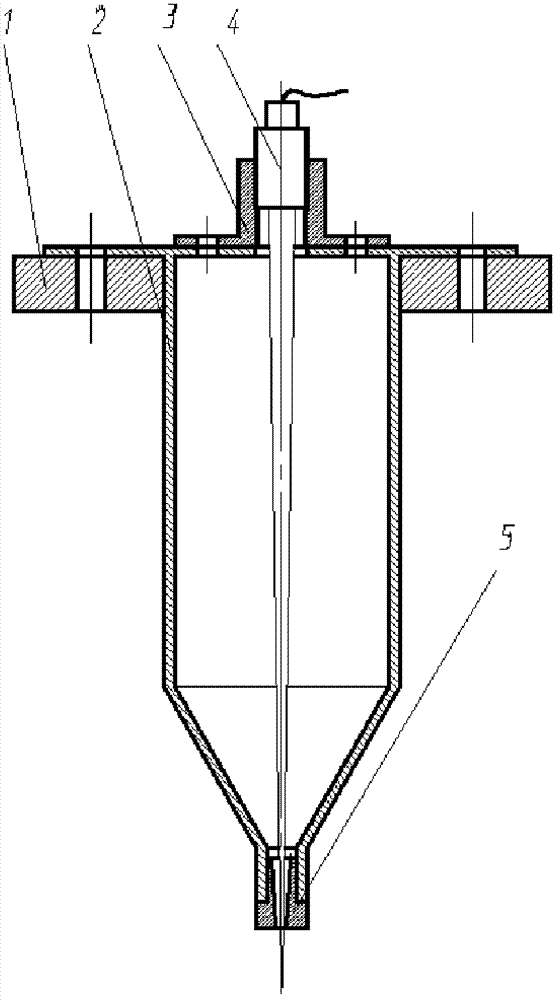
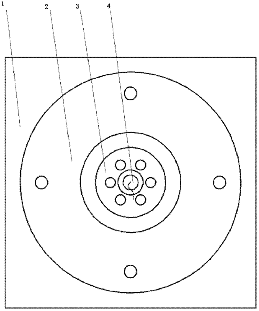
[0029] Such as Figure 1-6 As shown, an electrohydrodynamic jet printing coaxial nozzle of the present invention includes a probe placement platform 1 , a nozzle 2 , a support seat 3 , a metal probe 4 , and a lip sleeve 5 .

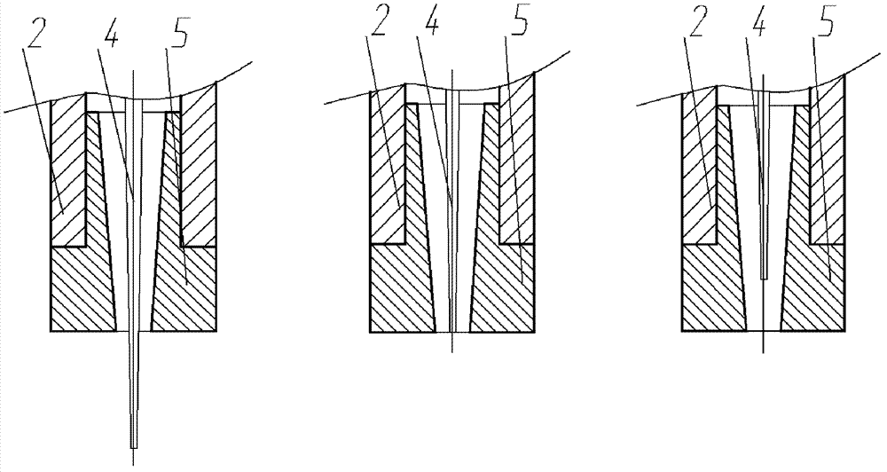
[0030] The nozzle 2 is fixed on the probe placement platform 1, the support seat 3 is installed on the upper end of the nozzle 2, the lip cover 5 is set on the nozzle at the lower end of the nozzle 2, and the upper needle end of the metal probe 4 is set on the support seat 3. In the central threaded hole, the needle body is placed in the inner cavity of the nozzle 2, the axis of the needle body is coaxial with the central axis of the nozzle 2, and the needle tip of the lower part of the probe passes through the inner through hole of the lip sleeve 5 and protrudes out of the nozzle 2.

[0031] The metal probe 4 i...


PUM


Abstract

The invention discloses a coaxial jet head for electro-hydrodynamic jet printing, which comprises a probe-placed platform, a nozzle, a support seat, a metal probe and a lip sleeve, wherein the nozzle is fixedly arranged on the probe-placed platform, the support seat is arranged at the upper end of the nozzle, the lip sleeve is sleeved on a spout at the lower end of the nozzle, an probe sleeve at the upper end of the metal probe is sleeved in a central screwed hole of the support seat, a probe body is arranged in an inner cavity of the nozzle, the axis line of the probe body and the central axis line of the nozzle are coaxial, and a probe tip at the lower part of the metal probe passes through a through hole in the lip sleeve and stretches out the nozzle. The invention also discloses the application of the jet head in preparing micro-nano fiber. By using the coaxial jet head disclosed by the invention, the control precision of ink supply amount can be increased; and through replacing the lip sleeve, a serialized jet head can be formed, thereby solving the problem that small-inside-diameter nozzles are blocked easily and solutions in large-inside-diameter nozzles easily naturally drop, solving the problem that a solid metal probe can not be continuously supplied with ink, and effectively reducing the critical voltage value of process-required exerted external voltage.

Description

technical field [0001] The invention belongs to the field of inkjet printing, and in particular relates to a spray head of an electrohydrodynamic jet printing device and its application. technical background [0002] Electrohydrodynamic printing (EHD) is driven by an electric field to generate extremely fine jets from the top of the liquid cone in a "pull" manner, forming sprays, fibers and droplets respectively, corresponding to the three types of electrospraying, electrospinning and electrojet printing. Printing mode. EHD printing has many unique advantages, such as sub-micron resolution can be achieved, particles or polymer solutions are easy to spray out without clogging, etc. It is very suitable for complex and high-precision patterning, and has a wide range of applications in flexible electronics manufacturing Prospects, such as electrospraying, electrospinning, and electrospray printing can be used to prepare thin film layers, device interconnections, and electrodes ...

Claims


Application Information

Patent Timeline
Patent Type & Authority Patents(China)
IPC IPC(8): B41J2/14
Inventor 黄永安尹周平潘艳桥布宁斌
Owner HUAZHONG UNIV OF SCI & TECH
Why Eureka
Try Eureka