supersonic rotary engine

A rotary engine, supersonic technology, applied in the field of thermal energy and power, can solve the problems of waste and low efficiency of power system

Inactive Publication Date: 2011-12-14
靳北彪
View PDF13 Cites 27 Cited by
  • Summary
  • Abstract
  • Description
  • Claims
  • Application Information

AI Technical Summary

Problems solved by technology

This thermal power system is simple in structure and high in efficiency, but the supersonic jet channel body is difficult to use as an engine that outputs rotational power, because when the supersonic jet channel body rotates at a high linear speed, a huge centrifugal force will be generated, and the current It is difficult for some materials to withstand this huge centrifugal force
If the supersonic jet channel body cannot be made to perform circular motion at a high linear velocity, only a part of the kinetic energy of the gas ejected from the supersonic jet channel body will be changed into the kinetic energy of the supersonic jet channel body and what the supersonic jet channel body does to the outside. work, while the other part or even most of it still exists in the gas as the kinetic energy of the gas. In the end, this part of the gas kinetic energy does not work externally, but is wasted in vain.
Therefore, the efficiency of the power system that obtains the recoil force from the supersonic jet and then uses the recoil force to perform work is relatively low.

Method used


Image

  • supersonic rotary engine
  • supersonic rotary engine
  • supersonic rotary engine

Examples


Embodiment 1

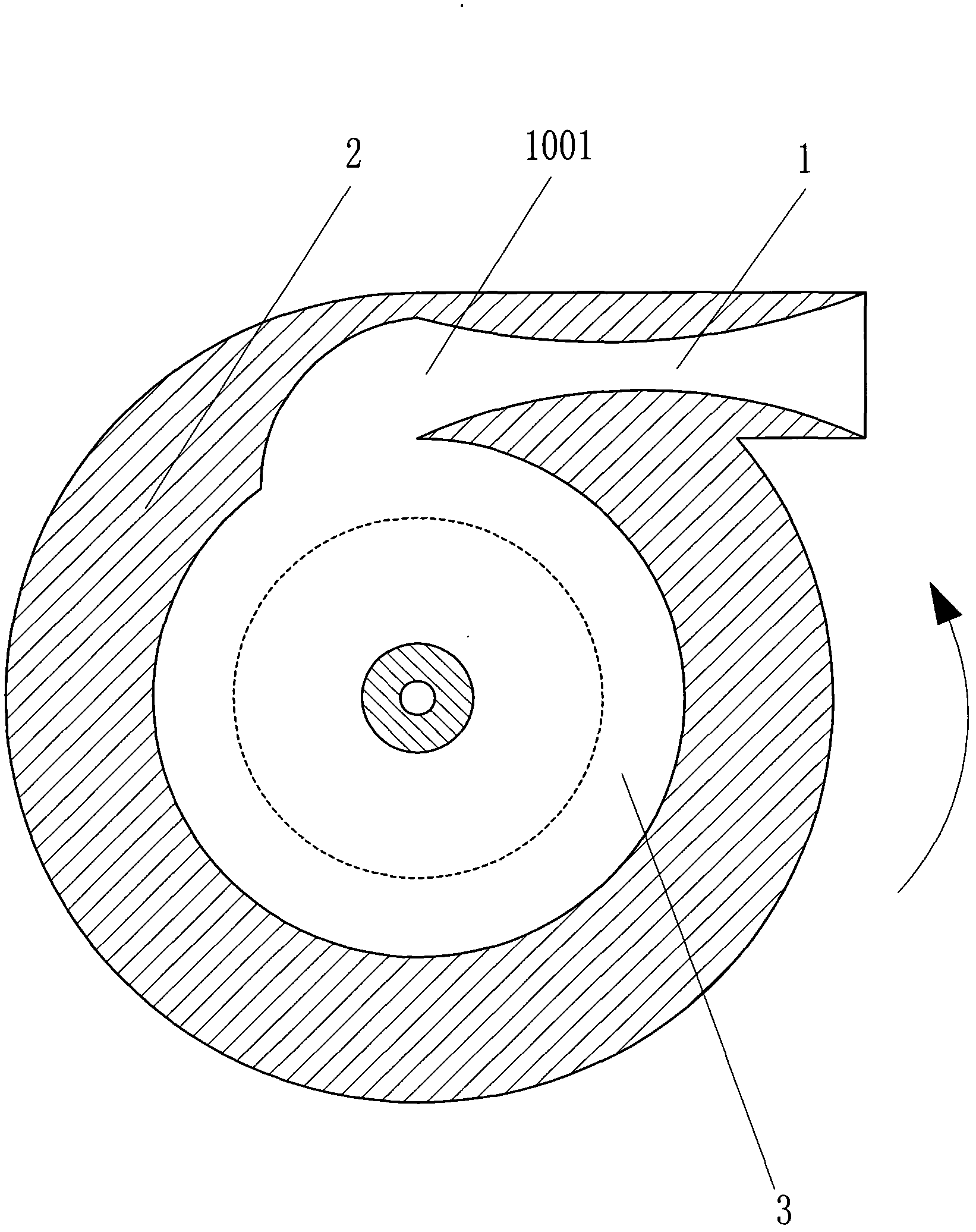
[0092] Such as figure 1The supersonic rotary engine shown includes a supersonic injection channel 1, a rotating structure 2 and a high-pressure working medium source 3. The supersonic injection channel 1 is arranged on the rotating structure 2, and the working medium inlet 1001 of the supersonic injection channel 1 is connected to the The high-pressure working medium source 3 is connected, and the pressure bearing capacity of the high-pressure working medium source 3 is greater than 2MPa. The injection direction of the supersonic jet channel 1 is generally directed at the tangent of the rotation circle of the rotating structure 2, and the rotating structure 2 outputs power to the outside. . When the supersonic rotary engine is working normally, the velocity of the airflow ejected from the supersonic injection channel is greater than Mach 2, and the static pressure of the airflow ejected from the supersonic injection channel is equal to the ambient pressure at the exit of the s...

Embodiment 2

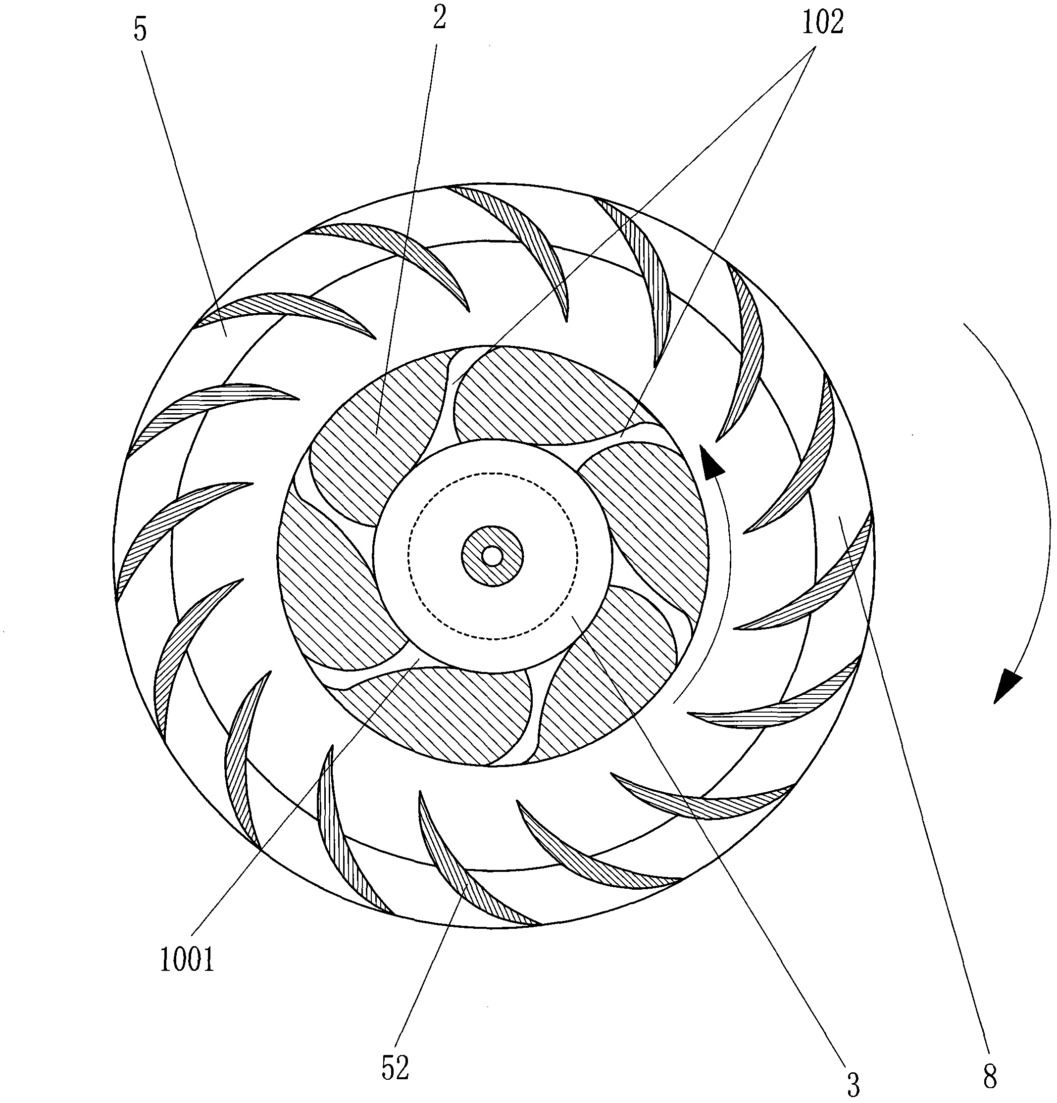
[0095] Such as figure 2 The difference between the shown supersonic rotary engine and Embodiment 1 is that the supersonic injection channel is set as the Laval nozzle 102, and the supersonic rotary engine also includes a passive rotating structure 5, and an impact is set on the passive rotating structure 5. The transmission structure 52, the jet air flow of the supersonic jet channel 1 impacts the passive rotating structure 5 on the impact transmission structure 52 to drive the passive rotating structure 5 to rotate, and the passive rotating structure 5 also outputs power to the outside. The passive rotating structure 5 is arranged on the periphery of the rotating structure 2 , and the working medium inlets 1001 of two or more Laval nozzles 102 communicate with a high-pressure working medium source 3 . The passive rotating structure 5 is provided with a diversion channel 8, and the jet flow of the supersonic jet channel 1 impacts and drives the passive rotating structure 5 an...

Embodiment 3

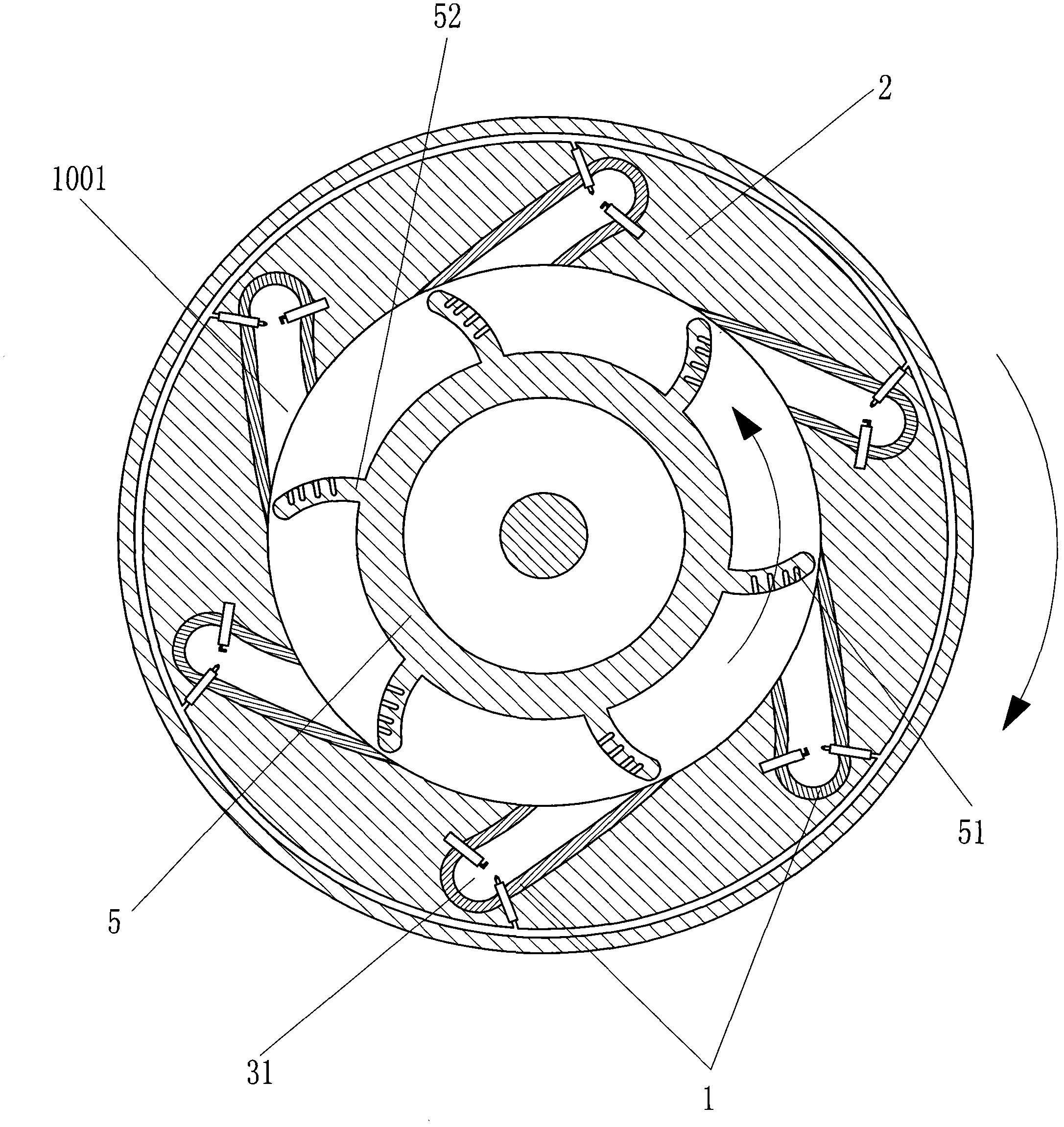
[0097] Such as image 3 The difference between the shown supersonic rotary engine and Embodiment 2 is that the high-pressure working medium source is set as a rocket combustion chamber 31, and the rotating structure 2 is arranged on the periphery of the passive rotating structure 5, and the passive rotating structure 5 is supersonic. An air-cushion buffer structure 51 is provided on the part where the high-speed jet stream impacts the sonic jet channel 1, and the air-cushion buffer structure 51 reduces the reflection of the high-speed jet stream. When the supersonic rotary engine is working normally, the velocity of the airflow ejected from the supersonic injection channel is greater than Mach 4.


PUM


Abstract

The invention discloses a supersonic rotor engine, which comprises a supersonic jet channel (1), a rotating structure body (2) and a high pressure working medium source (3), wherein the supersonic jet channel (1) is formed on the rotating structure body (2); a working medium inlet (1001) of the supersonic jet channel (1) is communicated with the high pressure working medium source (3); the loading capacity of the high pressure working medium source (3) is higher than 2MPa; the jet of the supersonic jet channel (1) is generally oriented by a tangent line of rotating circumferential of the rotating structure body (2); and the rotating structure body (2) externally outputs power. The supersonic rotor engine has a simple structure, low manufacturing cost and high reliability, and greatly improves the efficiency of conventional engines.

Description

technical field [0001] The invention relates to the field of thermal energy and power, in particular to a rotary engine. Background technique [0002] Whether it is a piston or a turbine engine, its structure is relatively complicated and its efficiency is not high. And the supersonic jet channel body (such as rocket nozzle, etc.) as the thrust engine can convert thermal energy into the kinetic energy of supersonic gas with very high efficiency, as long as the motion speed of the supersonic jet channel body is high enough, very high energy can be obtained. High propulsion efficiency, when the moving speed of the supersonic jet channel body is close to the moving speed of the supersonic gas ejected from the supersonic jet channel body, all the kinetic energy of the supersonic gas can be completely transformed into the supersonic jet channel body The sum of the energy of the kinetic energy and the work done by the body of the supersonic jet channel. This thermal power system...

Claims


Application Information

Patent Timeline
Patent Type & Authority Applications(China)
IPC IPC(8): F02K9/97F02K7/14F02K1/00F02K9/62F02K9/60
CPCF01D1/22F01D1/32
Inventor 靳北彪
Owner 靳北彪
Why Eureka
Try Eureka