
A device and method for two-dimensional direction of arrival estimation based on L-shaped array

A technology of direction estimation and two-dimensional waves, which is applied to radio wave direction/deviation determination systems, direction finders using radio waves, and components of radio wave directors, etc., which can solve poor estimation performance, large error in estimation performance, high complexity problems

Inactive Publication Date: 2011-12-14
XI AN JIAOTONG UNIV
View PDF2 Cites 20 Cited by
  • Summary
  • Abstract
  • Description
  • Claims
  • Application Information

AI Technical Summary

Problems solved by technology

Most of the structures and methods currently used are based on two-dimensional sensor arrays composed of two or more linear arrays. These sensor arrays with specific structures can obtain two-dimensional space direction of arrival estimates through the one-dimensional direction of arrival estimation method. But these methods require pairing of elevation and azimuth angles; pairing is still required even if the propagation algorithm is modified based on eigenvalue decomposition
In addition, although the method based on singular value decomposition can realize the automatic pairing process of two-dimensional DOA, however, even in the case of uncorrelated signals, if the number of samples is small, the performance of this kind of method for azimuth estimation is not good, or the signal power is required. prior information, and due to the use of joint singular value decomposition and optimization involving nonlinear constraint functions, the complexity of the method is high, so these algorithms based on singular value decomposition have their own defects, even if the improved one A method based on a specific cross-correlation matrix, which can correctly estimate the azimuth and elevation angles, but its estimation performance is seriously affected by the "virtual angle", resulting in large errors

Method used


Image

  • A device and method for two-dimensional direction of arrival estimation based on L-shaped array
  • A device and method for two-dimensional direction of arrival estimation based on L-shaped array
  • A device and method for two-dimensional direction of arrival estimation based on L-shaped array

Examples


Embodiment Construction

[0039] The present invention will be described in more detail below in conjunction with the accompanying drawings and embodiments.

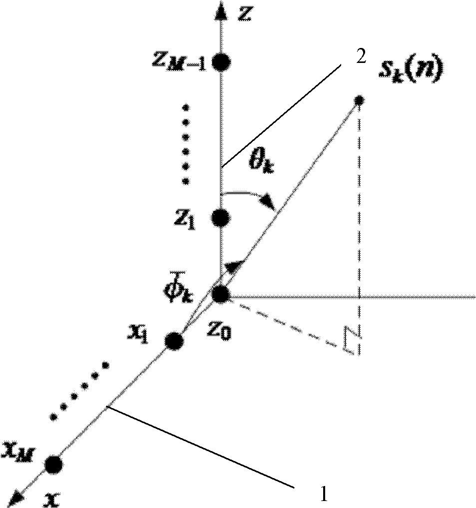
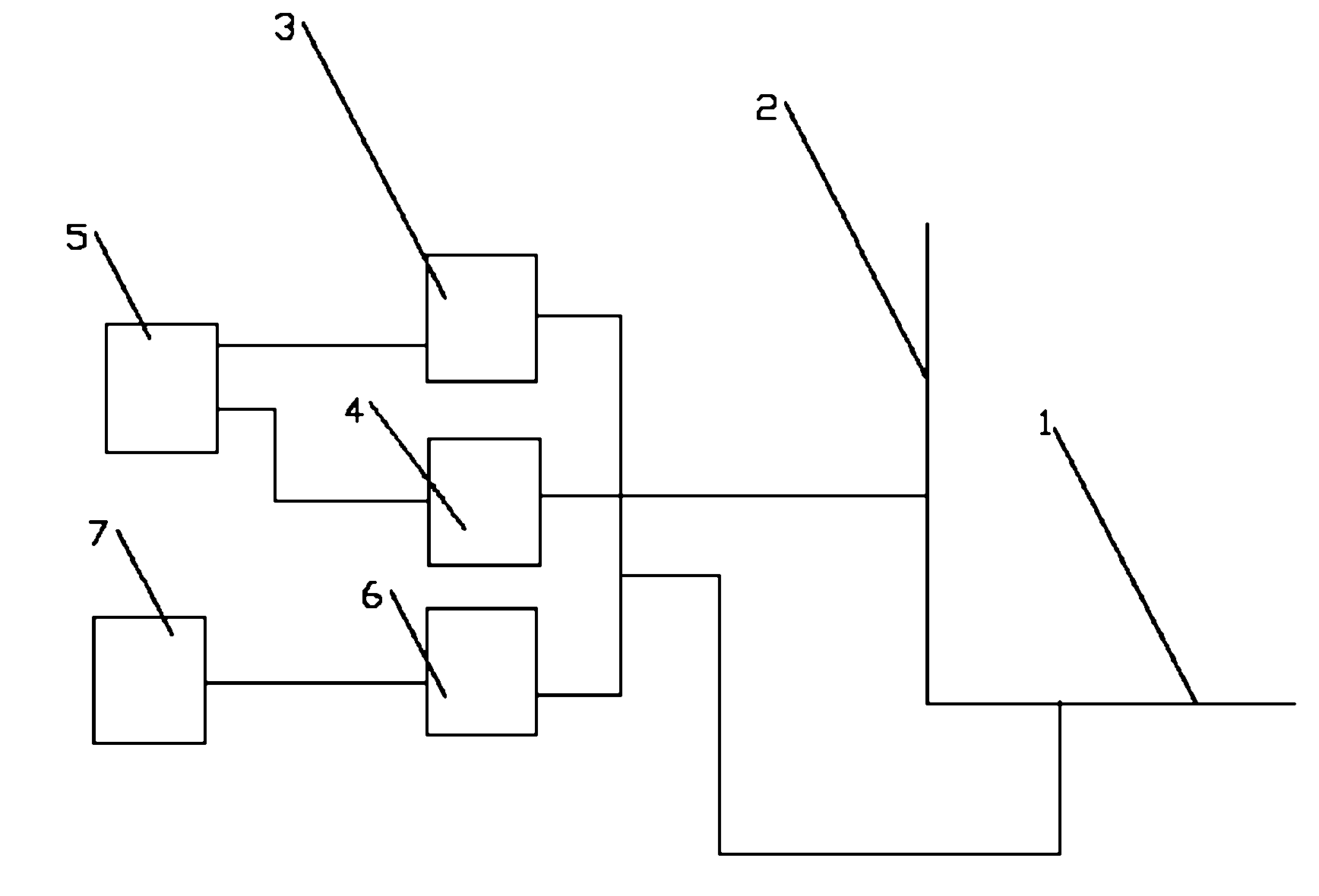
[0040] Such as figure 1 and figure 2 As shown, the device for estimating the two-dimensional direction of arrival based on the L-shaped array includes a rectangular L-shaped array antenna. The rectangular L-shaped array antenna is one end of the linear sub-array antenna 1 equidistant in the longitudinal x direction and the One end of the z-direction equidistant linear sub-array antenna 2 is vertically connected, wherein the longitudinal x-direction equidistant linear sub-array antenna 1 includes first longitudinal x-direction antenna elements x arranged in pairs equidistant along the longitudinal x direction 1 , the second longitudinal x-direction antenna element x 2 ,..., the Mth vertical x-direction antenna element x M It consists of a total of M antenna elements, and the linear sub-array antenna 2 equidistant in the vertical z direction in...


PUM


Abstract

The invention relates to an L-shaped array-based two-dimensional wave arrival direction estimating device and a method thereof. The method comprises the following steps of: acquiring cross correlation matrixes by using a right angle folding ruler L-shaped array antenna which is formed by vertically connecting one end of an equal-distance linear sub-array antenna in a longitudinal direction x withone end of an equal-distance linear sub-array antenna in a vertical direction z, and according to observation data which is acquired from the equal-distance linear sub-array antenna in the longitudinal direction x and the equal-distance linear sub-array antenna in the vertical direction z; independently acquiring an azimuth angle estimation value and an elevation angle estimation value through linear operation; and automatically accomplishing the process of matching an azimuth angle with an elevation angle by minimizing an azimuth angle and elevation angle cost function. Thus, the characteristic value decomposition process is avoided, complexity is reduced, a few estimation errors are generated, and precision is high.

Description

technical field [0001] The present invention relates to a device and method for two-dimensional direction of arrival, in particular to a device and method for estimating two-dimensional direction of arrival based on an L-shaped array. Background technique [0002] Array signal processing has developed rapidly in recent years, and its applications involve many military and national economic fields such as radar, communication, and sonar. It arranges multiple antenna elements at different positions in space to form an antenna array, and uses this antenna array to receive and process space radio waves, and extract the radio wave signals received by the array and their characteristic information. Array signal processing has the characteristics of flexible beam steering, high signal gain, strong anti-interference ability and high spatial super-resolution ability, etc., which has attracted people's attention and is more and more widely used. [0003] A typical problem to be solve...

Claims


Application Information

Patent Timeline
IPC IPC(8): G01S3/12G01S3/14
Inventor 王光敏辛景民陶浩郑南宁
Owner XI AN JIAOTONG UNIV
Learn More