
Battery liquid injection device and liquid injection method

A liquid injection device and battery technology, which is applied to battery pack components, circuits, electrical components, etc., can solve the problems of low liquid injection efficiency, slow operation speed, limitations, etc., and achieve high liquid injection efficiency, improve efficiency, and continuous. The effect of a high degree of work

Active Publication Date: 2011-12-14
SHENZHEN AMPOWER NEW ENERGY CO LTD
View PDF5 Cites 8 Cited by
  • Summary
  • Abstract
  • Description
  • Claims
  • Application Information

AI Technical Summary

Problems solved by technology

This natural filling method has defects such as very slow filling speed, easy overflow of electrolyte, and frequent battery leakage and underfilling, which limits the production capacity of the liquid injection process and directly leads to problems such as open circuit, low capacity, and large internal resistance. Series of defective batteries
In addition, this method is also affected by many factors such as the speed of alkali absorption of the diaphragm, the tightness of the battery electrode group, air humidity, and human factors.
The centrifugal liquid injection method solves the above problems to a certain extent. It uses a solid-liquid separation device to evenly distribute individual batteries around the rotating shaft, and uses the centrifugal force generated when the rotating shaft moves to accelerate the flow of electrolyte. However, this method operates at a faster speed. Slow, low degree of continuity, unable to adapt to the requirements of industrial mass production of batteries, resulting in low liquid injection efficiency

Method used


Image

  • Battery liquid injection device and liquid injection method
  • Battery liquid injection device and liquid injection method
  • Battery liquid injection device and liquid injection method

Examples


Embodiment Construction

[0026] The specific embodiments of the present invention will be described below mainly in conjunction with the accompanying drawings.

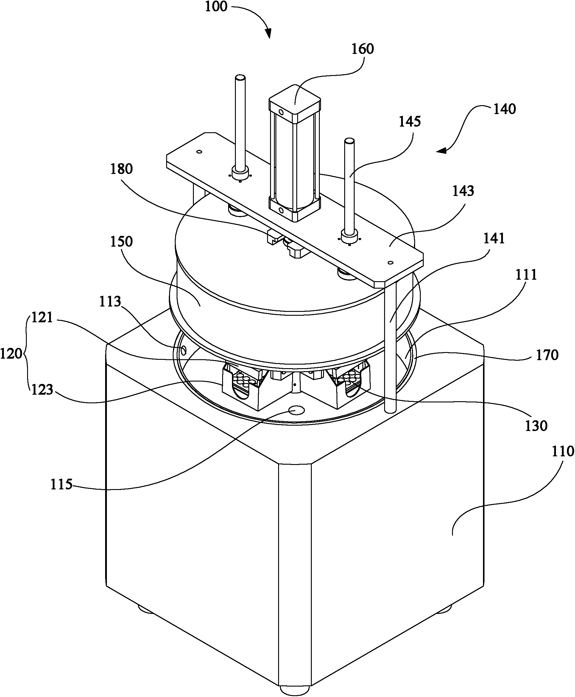
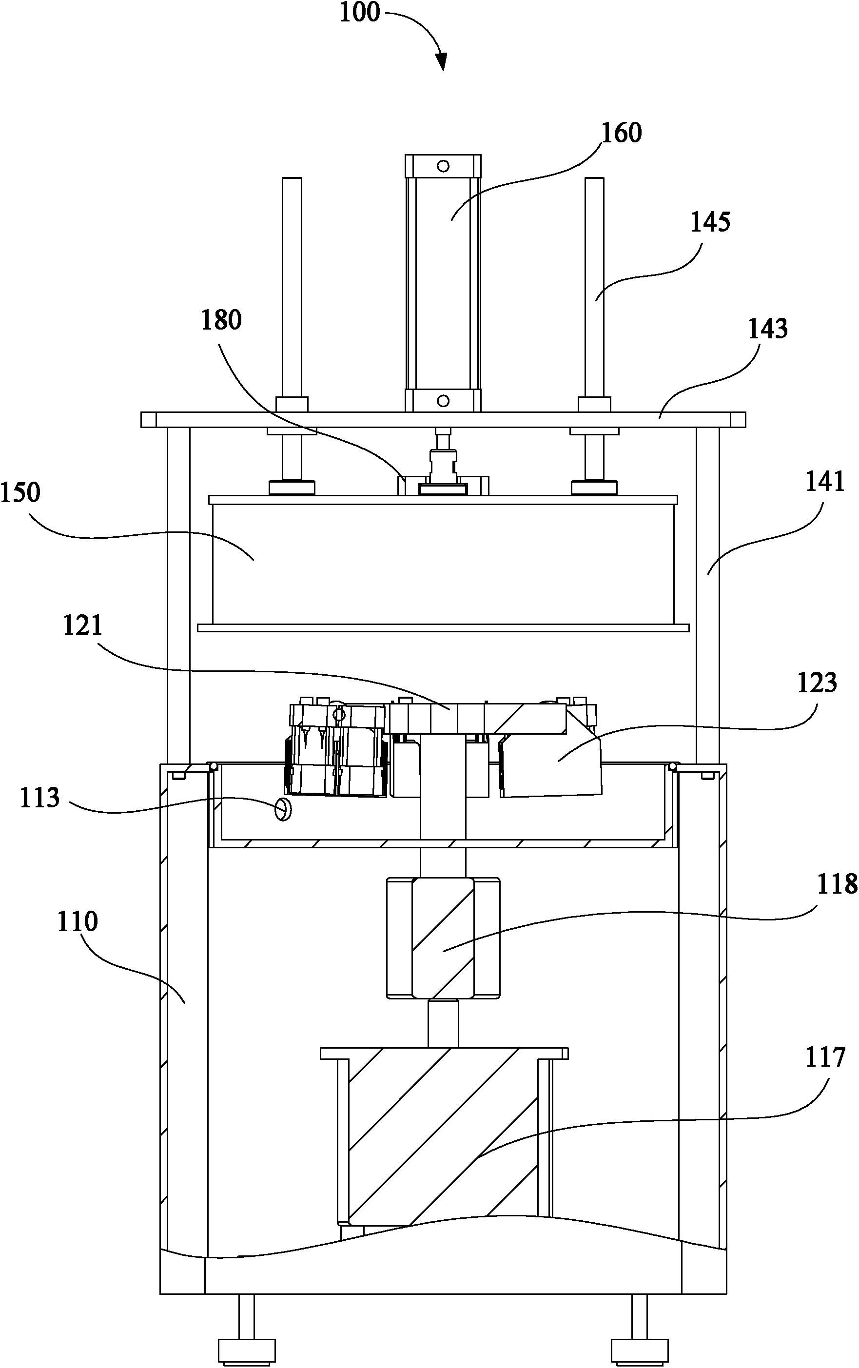
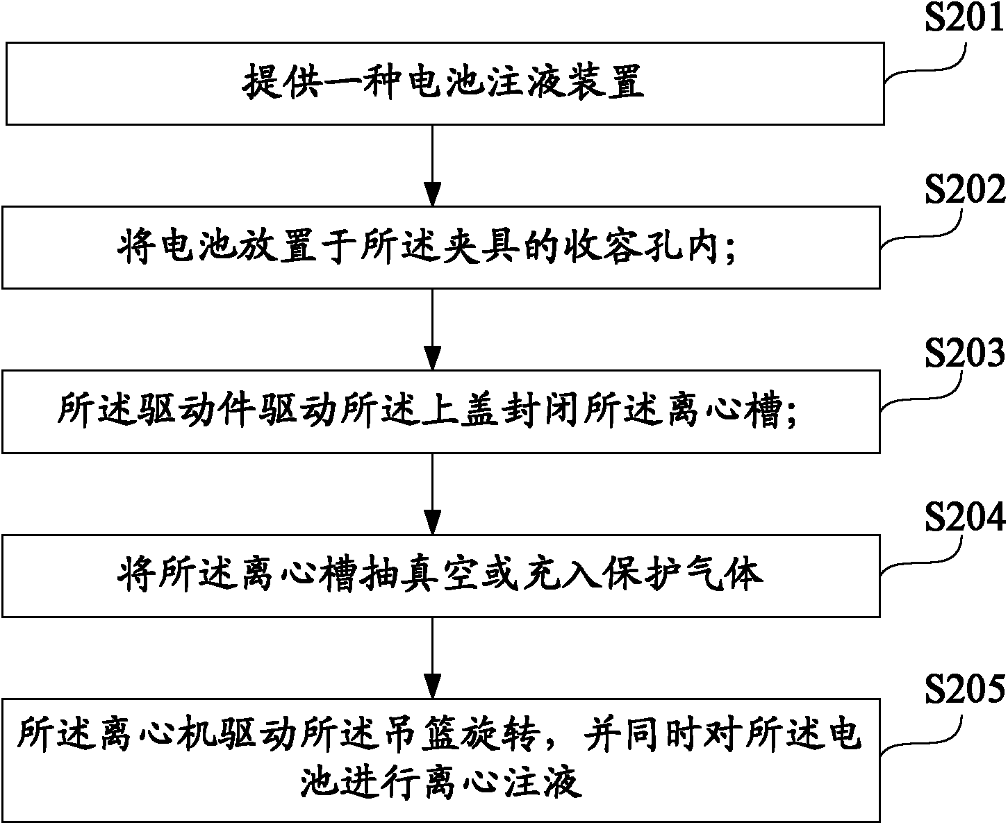
[0027] see figure 1 and figure 2 , The battery liquid injection device 100 of this embodiment is used to inject the electrolyte into the battery, which includes a centrifuge 110 , a hanging basket 120 , a clamp 130 , a support base 140 , an upper cover 150 and a driving member 160 .

[0028] The centrifuge 110 has a centrifuge tank 111 . The centrifuge tank 111 is approximately cylindrical.

[0029] The hanging basket 120 is accommodated in the centrifugal tank 111 of the centrifuge 110 , and the centrifuge 110 can drive the hanging basket 120 to rotate. Specifically, in this embodiment, the hanging basket 120 includes a fixing bracket 121 and a plurality of storage boxes 123 fixed on the periphery of the fixing bracket 121 , and the clamp 130 can be placed in the storage boxes 123 .

[0030] It can be understood that the hanging basket ...


PUM


Abstract

The invention discloses a battery electrolyte injecting device, which is used for injecting electrolyte into a battery. The battery electrolyte injecting device comprises a centrifuge, a hanging basket, a clamp, a support seat, an upper cover and a driving part, wherein the centrifuge has a centrifugal groove; the hanging basket is accommodated in the centrifugal groove; the centrifuge can drive the hanging basket to rotate; the clamp is arranged on the hanging basket, and is provided with an accommodating hole for accommodating the battery; the support seat is fixed on the centrifuge and positioned above the centrifugal groove; the upper cover covers the opening of the centrifugal groove; and the driving part is fixed on the support seat, is fixedly connected with the upper cover, and can drive the upper cover to cover or uncover the opening of the centrifugal groove. The electrolyte injecting efficiency of the battery electrolyte injecting device is high. The invention also providesa battery electrolyte injecting method.

Description

【Technical field】 [0001] The invention relates to battery manufacturing equipment, in particular to a battery liquid injection device and a liquid injection method. 【Background technique】 [0002] At present, the traditional liquid injection method of secondary batteries such as hydrogen nickel and cadmium nickel is generally manual liquid injection and natural liquid injection, that is, after the electrolyte is manually injected, the electrolyte will naturally flow into the battery under the action of its gravity and be absorbed by it. . This natural filling method has defects such as very slow filling speed, easy overflow of electrolyte, and frequent battery leakage and underfilling, which limits the production capacity of the liquid injection process and directly leads to problems such as open circuit, low capacity, and large internal resistance. Series of defective batteries. In addition, this method is also interfered by many factors such as the alkali absorption spee...

Claims


Application Information

Patent Timeline
Patent Type & Authority Applications(China)
IPC IPC(8): H01M2/36
CPCY02E60/12Y02E60/10
Inventor 李文良王小明韩晓辉刘峰陈艳熊胜任相江峰
Owner SHENZHEN AMPOWER NEW ENERGY CO LTD
Learn More